2.19
Date Code 20170814 Instruction Manual SEL-700G Relay
Installation
Rear-Panel Connections
Rear-Panel Connections
Rear-Panel and
Side-Panel Diagrams
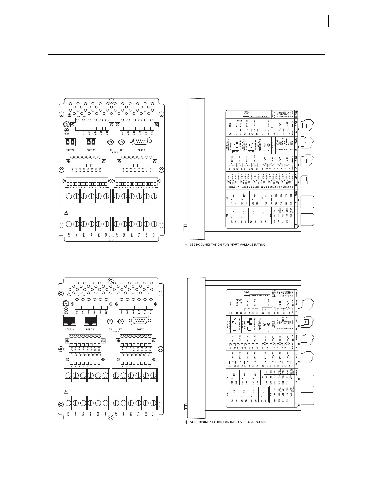
The physical layout of the connectors on the rear-panel and side-panel
diagrams of three sample configurations of the SEL-700G are shown in
Figure 2.8, Figure 2.9, and Figure 2.10.
Figure 2.8 SEL-700G1+ With Dual-Fiber Ethernet, Fast Hybrid 4 DI/4 DO, 10 RTDs, 3 ACI/2 AVI, 4 ACI/3 AVI
(MOT 0700G11ACA9X76850830)
Figure 2.9 SEL-700GT+ With Dual Copper Ethernet, 4 DI/4 DO, 8 DO, 3 ACI/4 AVI, 4 ACI/3 AVI (MOT
0700GT1A2X75850630)
E02
E03
E04
E05
E06
E01
E08
E09
E10
E11
E12
E07
D30
D16
D15
D01
i4491a
i4488a
(a) Rear-Panel View (b) Side-Panel View
(a) Rear-Panel View (b) Side-Panel View
E02
E03
E04
E05
E06
E01
E08
E09
E10
E11
E12
E07
D09
D16
D01
D08
i4492a
i4489a



 To Next Page