2.24
SEL-700G Relay Instruction Manual Date Code 20170814
Installation
AC/DC Control Connection Diagrams
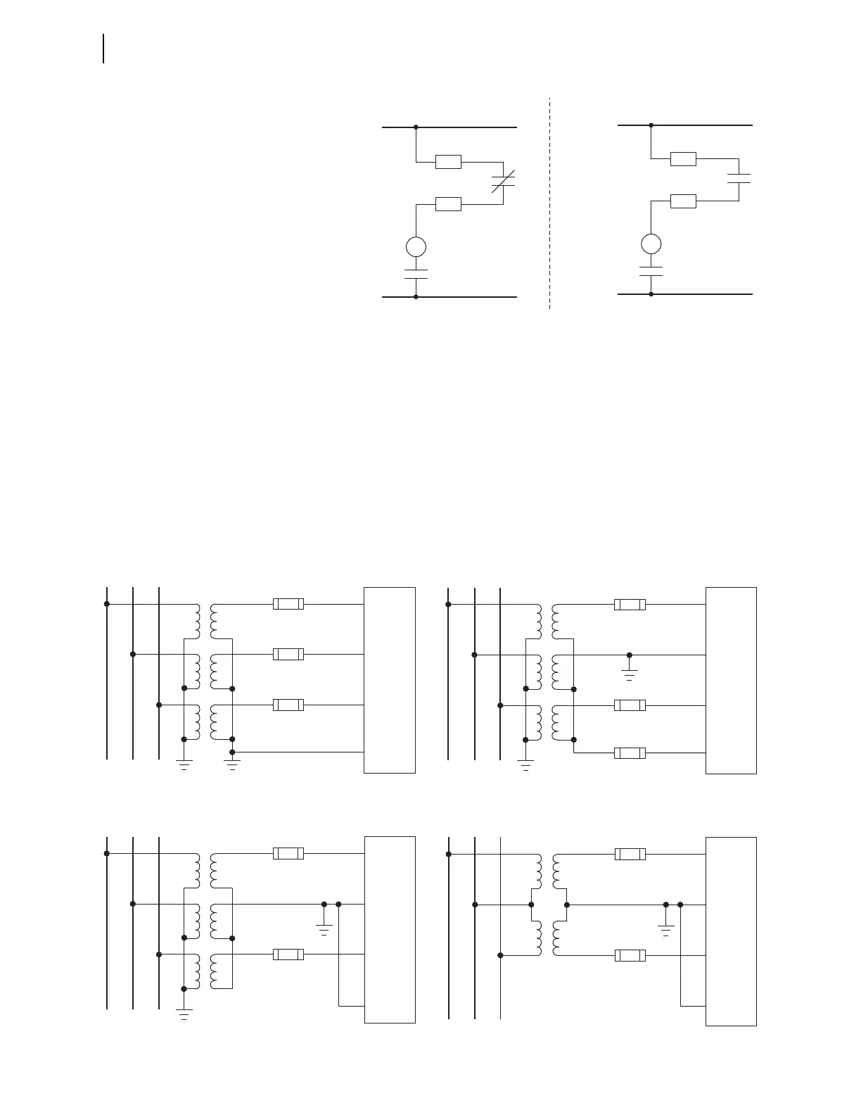
Figure 2.15 OUT103 Contact Fail-Safe and Nonfail-Safe Options
Voltage Connections
With the voltage inputs option, the three-phase voltages can be connected
either 3-wire (delta) or 4-wire (wye). Figure 2.16 (a–d) shows typical methods
for connecting three-phase voltages. The relay also allows you to connect
external zero-sequence voltage (3V0) to VS-NS or VN-NN inputs, as shown in
Figure 2.16 (e) and Figure 2.16 (f), respectively, when the terminal PTs are
delta connected. Refer to SEL-700G1+ Generator Relay Application
Example 2, Illustrating the 67N Element and Section 4: Protection and Logic
Functions for more details.
Nonfail-safe
OUT103FS = N
52A
Breaker Trip Coil
TC
A08
A07
A07
TC
52A
Fail-Safe
(Electrically Held Open)
OUT103FS= Y
Circuit Breaker
Breaker Trip Coil
A09
(b) Wye-Wye VT 4-Wire Connection (Set DELTAY_X := Wye)
(d) Open-Delta VT 3-Wire Connection (Set DELTAY_X := Delta)
AB
C
ZO9
Z10
Z11
Z12
SEL-700G
F1
F3
(c) Wye-Wye VT 3-Wire Connection (Set DELTAY_X := Delta)
AB
C
ZO9
Z10
Z11
Z12
SEL-700G
F1
F3
(a) Wye-Wye VT 4-Wire Connection (Set DELTAY_X := Wye)
AB
C
ZO9
Z10
Z11
Z12
SEL-700G
F1
F2
F3
AB
C
ZO9
Z10
Z11
Z12
SEL-700G
F1
FN
F3
Notes:
1. Voltage circuit should be grounded in the relay cabinet.
2. Slot Z connections are shown; Slot E connections are similar.



 To Next Page