1.13
Date Code 20170814 Instruction Manual SEL-700G Relay
Introduction and Specifications
Specifications
AC Output Ratings
Maximum Operational
Vo l t a g e ( U
e
) Rating: 240 Vac
Insulation Voltage (U
i
)
Rating (excluding
EN 61010-1): 300 Vac
Contact Rating Designation: B300
Utilization Category: AC-15
Voltage Protection Across
Open Contacts: 270 Vac, 40 J
Fast Hybrid (High-Speed, High-Current Interrupting)
DC Output Ratings
Rated Operational Voltage: 250 Vdc
Rated Voltage Range: 19.2–275 Vdc
Rated Insulation Voltage: 300 Vdc
Make: 30 A @ 250 Vdc per IEEE C37.90
Continuous Carry: 6 A @ 70°C
4A @ 85°C
1-Second Rating: 50 A
Open State Leakage Current: <500 µA
MOV Protection (Maximum
Voltage): 250 Vac/330 Vdc
Pickup Time: <50 s, resistive load
Dropout Time: 8 ms, resistive load
Break Capacity (10,000 Operations) per IEC 60255-0-20:1974:
48 Vdc 10.0 A L/R = 40 ms
125 Vdc 10.0 A L/R = 40 ms
250 Vdc 10.0 A L/R = 20 ms
Cyclic Capacity (4 cycles in 1 second, followed by 2 minutes idle for
thermal dissipation) per IEC 60255-0-20:1974:
48 Vdc 10.0 A L/R = 40 ms
125 Vdc 10.0 A L/R = 40 ms
250 Vdc 10.0 A L/R = 20 ms
AC Output Ratings
See AC Output Ratings for Standard Contacts.
Optoisolated Control Inputs
When Used With DC Control Signals
250 V: ON for 200–312.5 Vdc
OFF below 150 Vdc
220 V: ON for 176–275 Vdc
OFF below 132 Vdc
125 V: ON for 100–156.2 Vdc
OFF below 75 Vdc
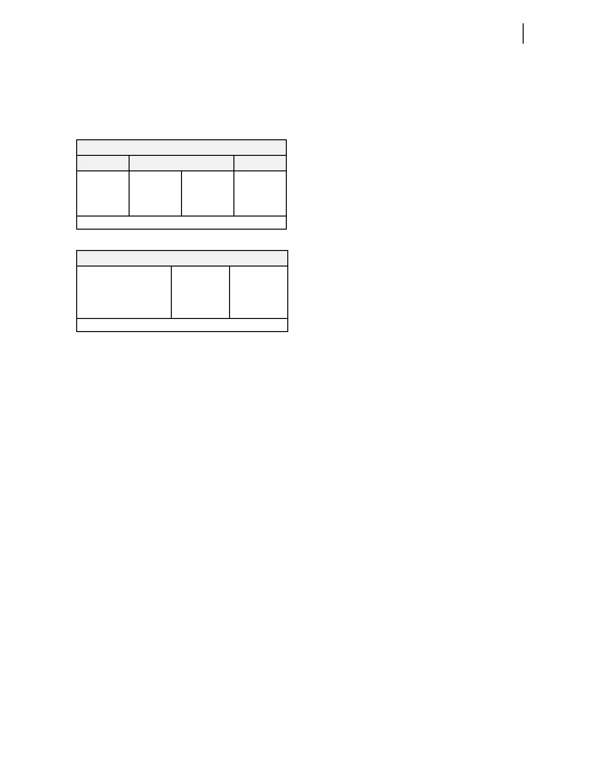
B300 (5 A Thermal Current, 300 Vac Max)
Maximum Current Max VA
Voltage 120 Vac 240 Vac
—
Make 30 A 15 A
3600
Break 3 A 1.5 A
360
PF < 0.35, 50–60 Hz
AC-15
Operational Voltage (Ue) 120 Vac 240 Vac
Operational Current (Ie) 3 A 1.5 A
Make Current 30 A 15 A
Break Current 3 A 1.5 A
Electromagnetic loads > 72 VA, PF < 0.3, 50–60 Hz
110 V: ON for 88–137.5 Vdc
OFF below 66 Vdc
48 V: ON for 38.4–60 Vdc
OFF below 28.8 Vdc
24 V: ON for 15–30 Vdc
OFF for <5 Vdc
When Used With AC Control Signals
250 V: ON for 170.6–312.5 Vac
OFF below 106 Vac
220 V: ON for 150.2–275 Vac
OFF below 93.3 Vac
125 V: ON for 85–156.2 Vac
OFF below 53 Vac
110 V: ON for 75.1–137.5 Vac
OFF below 46.6 Vac
48 V: ON for 32.8–60 Vac
OFF below 20.3 Vac
24 V: ON for 14–30 Vac
OFF below 5 Vac
Current Draw at Nominal DC
Vo l t a g e :
2 mA (at 220–250 V)
4 mA (at 48–125 V)
10 mA (at 24 V)
Rated Impulse Withstand
Volt age (U
imp
): 4000 V
Analog Output (Optional)
1A0 4A0
Current: 4–20 mA ±20 mA
Voltage: — ±10 V
Load at 1 mA: — 0–15 k
Load at 20 mA: 0–300 0–750
Load at 10 V: — >2000
Refresh Rate: 100 ms 100 ms
% Error, Full Scale, at 25°C: <±1% <±0.55%
Select From: Analog quantities available in the relay
Analog Input (Optional)
Maximum Input Range: ±20 mA
±10 V
Operational range set by user
Input Impedance: 200 (current mode)
>10 k (voltage mode)
Accuracy at 25°C:
With user calibration: 0.050% of full scale (current mode)
0.025% of full scale (voltage mode)
Without user calibration: Better than 0.5% of full scale at 25°C
Accuracy Variation With
Temperature:
±0.015% per °C of full scale
(±20 mA or ±10 V)
Frequency and Phase Rotation
System Frequency: 50, 60 Hz
Phase Rotation: ABC, ACB
Frequency Tracking: 15–70 Hz
Time-Code Input
Format: Demodulated IRIG-B
On (1) State: V
ih
2.2 V
Off (0) State: V
il
0.8 V
Input Impedance: 2 k
Synchronization Accuracy
Internal Clock: ±1 µs
Synchrophasor Reports
(e.g., MET PM): ±10 µs
All Other Reports: ±5 ms



 To Next Page