AC
220 V
DC
12 V
50
60
70
80
90
100
40
30
20
10
0
4.5.1 - Checking the winding
You can check the winding insulation by performing a high
voltage test. In this case, you must disconnect all AVR wires.
CAUTION
Damage caused to the AVR in such conditions is not
covered by our warranty.
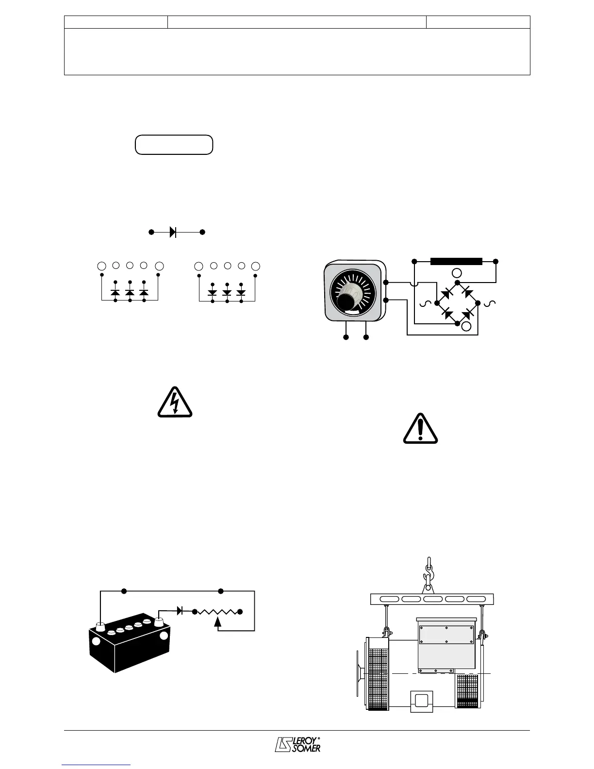
4.5.2 - Checking the diode bridge
4.5.3 - Checking the windings and rotating
diodes using separate excitation
During this procedure, make sure that the alternator is
disconnected from any external load and inspect the
terminal box to check that the connections are fully
tightened.
1) Stop the unit, disconnect and isolate the AVR wires.
2) There are two ways of creating an assembly with separate
excitation.
Assembly A: Connect a 12 V battery in series with a rheostat
of approximately 50 ohms - 300 W and a diode on both exciter
eld wires (5+) and (6-).
Assembly B: Connect a «Variac» variable power supply and
a diode bridge on both exciter eld wires (5+) and (6-).
Both these systems should have characteristics which are
compatible with the eld excitation power of the machine (see
the genset nameplate).
3) Run the unit at its rated speed.
4) Gradually increase the exciter eld supply current by
adjusting the rheostat or the Variac and measure the output
voltages on L1 - L2 - L3, checking the excitation voltage at no
load (see machine nameplate or ask for the factory test
report).
When the output voltage is at its rated value and balanced
within 1% for the rated excitation level, the machine is in good
working order. The fault therefore comes from the AVR or its
associated wiring (ie. sensing, auxiliary windings).
4.6 - Dismantling, reassembly
(see sections 5.4.1/5.4.2 & 5.4.3)
During the warranty period, this operation should only be
carried out in an LEROY-SOMER approved workshop or in
our factory, otherwise the warranty may be invalidated.
Whilst being handled, the alternator should remain
horizontal (translational movement of rotor not locked).
Check how much the alternator weighs (see section 4.9)
before choosing the lifting method.
The choice of lifting hooks or handles should be
determined by the shape of the lifting rings.
Assembly A
Diode 1A
Exciter eld
12 V battery
Anode
LSA 43.2 / 44.2 diode bridge
A diode in good working condition allows the current
to ow in only one direction, from anode to cathode.
Cathode
Assembly B
Diode 1A
Exciter eld
INSTALLATION AND MAINTENANCE
LSA 43.2 / 44.2 - 4-poLe
ALTeRNAToRS
3434 en -