Rostock MAX v2 User's Guide
Appendix B: Alternate Calibration Method
The calibration method I'm going to outline here was originally used in the 2
nd
Edition of the
Rostock MAX v2 Assembly Manual. With the introduction of the 3
rd
Edition, it was requested that I
utilize the same calibration process that the fine folks at SeeMeCNC use when calibrating the Orion
printers after they're built. Both methods achieve the same result and I'm merely including this
alternate method for those that are interested in using it.
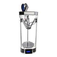
Note that unlike the original process that used a sheet of notebook paper, I want you to use a
0.009” feeler gauge. The photo below is the style you want to get:
Note that if you get a set that doesn't include the
0.009” gauge, you can use one similar in thickness.
It may be easier to use if you remove the feeler
gauge leaf from the set and rub the oil off of it – you don't
want the protective oil from contaminating the glass bed.
It will “re-oil” itself once it's replaced in the pack of gauge
leaves.
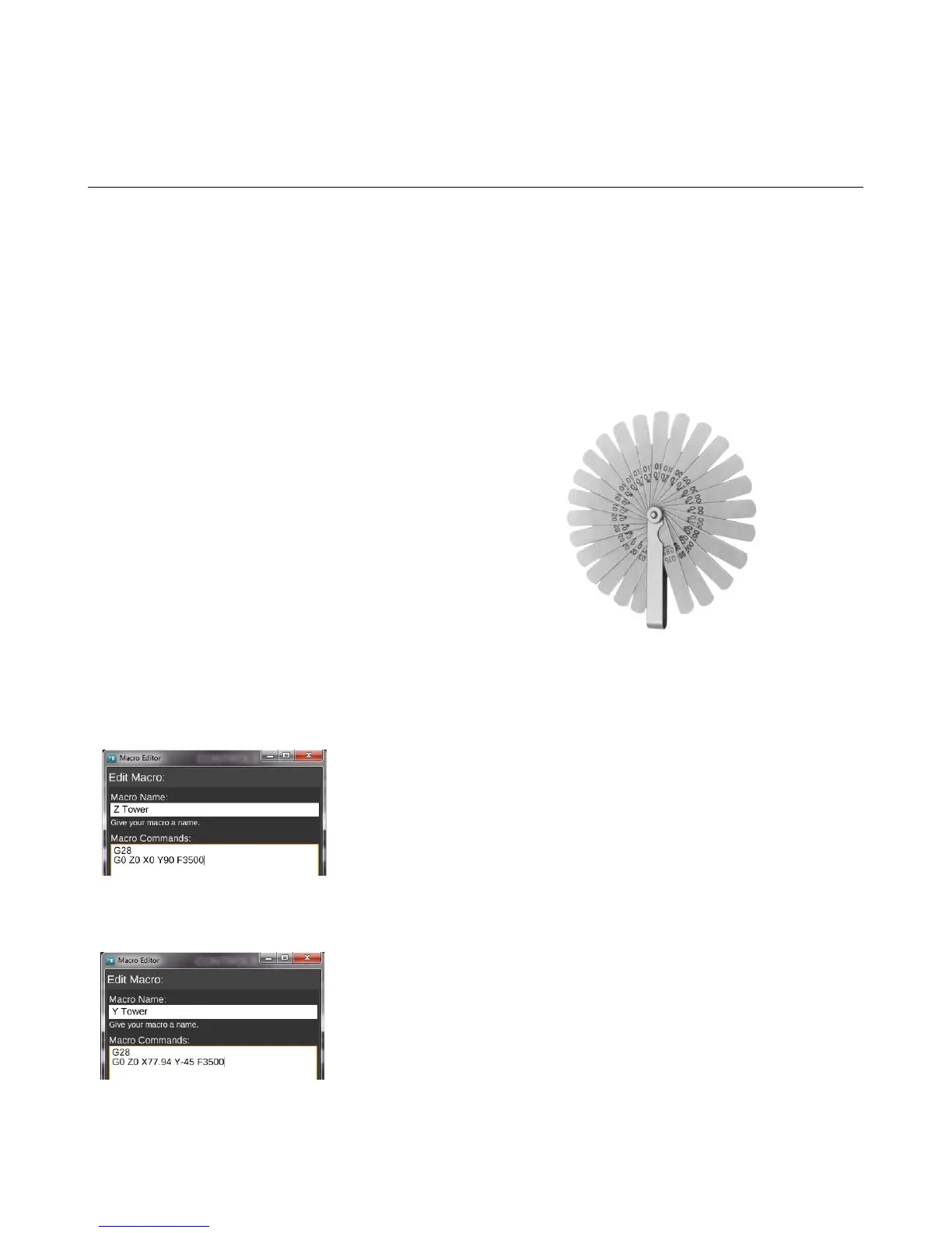
The first thing you'll do is create four new macros within MatterControl.
Create and name macro #1 “Z Tower” and use the following G-Code:
G28
G0 Z0 X0 Y90 F3500
Create and name macro #2, “Y Tower” and use the following G-Code:
G28
G0 Z0 X77.94 Y-45 F3500
Appendix B: Alternate Calibration Method - 115
Fig. A-1:Typical feeler gauges.
Fig. A-2: Z Tower.
Fig. A-3: Y Tower.