4 English
CONTENTS
Introduction ............................................................................................................................3
INSTRUCTIONS FOR USE
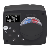
Appearance of the controller .................................................................................................5
Controller setup at the rst start-up .......................................................................................6
Step 1 – Language selection ........................................................................................6
Step 2 – Selection of hydraulic schematic ....................................................................6
Step 3 – setup of heating curve slope ..........................................................................7
Step 4 – selection of opening direction of the mixing valve ..........................................7
Graphic LCD ..........................................................................................................................8
Description and appearance of the display ..................................................................8
Symbols for the description of the operating mode ......................................................9
Symbols of user functions ............................................................................................9
Symbols for the display of temperatures and other data ............................................10
Symbols of protection functions .................................................................................10
Symbols for the display of communication between
interconnected devices ...............................................................................................10
Symbols for notications and warnings ......................................................................11
Display for help, notications and ERRORS .......................................................................11
Menu entry and navigation ..................................................................................................12
Building and menu description ............................................................................................12
Temperature setup .....................................................................................................14
User functions ............................................................................................................15
Operating mode selection ..........................................................................................16
Selection and setup of time programs ........................................................................17
Basic settings .............................................................................................................19
Data review ................................................................................................................21
INSTRUCTIONS FOR SERVICE SETTINGS
Controller parameters ..........................................................................................................22
User parameters .........................................................................................................22
Heating curve .............................................................................................................24
Service parameters ....................................................................................................27
SPECIAL PARAMETERS ...........................................................................................31
Factory settings ..........................................................................................................32
Description of the mixing cycle operation ...................................................................32
Operating modes in the event of sensor failure ..........................................................34
INSTALLATION INSTRUCTIONS
Controller installation ...........................................................................................................35
Electrical connection of the controller ..................................................................................36
Connection of temperature sensors ...........................................................................36
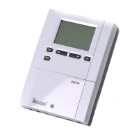
Connection of the RCD room unit ..............................................................................37
BUS connection of the AHC controllers ......................................................................37
BUS connection of the WDC and AHC controllers .....................................................38
BUS connection of the WXD and AHC controllers .....................................................38
Technical data: ...........................................................................................................39
Disposal of the old electrical and electronic equipment.......................................................40
Hydraulic schemes ...........................................................................................................155