34 English
The outdoor sensor is not connected or is defective.
- Heating:
The controller operates as the P-controller depending on the deviation of the room temperature.
- Cooling:
The controller operates as a room thermostat by limiting the minimum stand temperature.
The outdoor and room sensor are not connected or are defective.
- Heating:
The controller regulates the stand-pipe to a constant temperature:
- that is 25°C higher in radiator heating than the preferred day or night temperature,
- that is10°C higher in oor heating than the preferred day or night temperature.
- Cooling:
In the day-time interval, the stand temperature is equal the set-up S2.11 parameter, and in the
night-time interval, the cooling is switched o.
The room sensor is not connected or is defective.
The controller operates depending on the outdoor temperature without any inuence of the room
sensor.
The stand-pipe sensor is not connected or is defective.
- Heating:
The controller receives a signal that the temperature of the stand-pipe is 120°C. Heating is not
activated and the mixing valve closes.
- Cooling:
The controller receives a signal that the temperature of the stand-pipe is 4°C. Cooling is not
activated and the mixing valve closes.
The boiler sensor is not connected or is defective.
The controller receives a signal that the boiler temperature equals the set up maximum boiler
temperature. The regulation of the mixing valve is activated.
The return pipe sensor is not connected or is defective.
The controller operates without any inuence of the return pipe sensor.
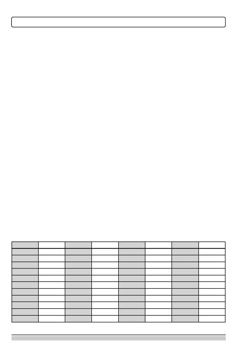
TABLE: Usability of temperature sensors Pt1000
Temp. [°C]
Resistance [Q]
Temp. [°C]
Resistance [Q]
Temp. [°C]
Resistance [Q]
Temp. [°C] Resistance [Q]
-20 922 35 1,136 90 1,347 145 1,555
-15 941 40 1,155 95 1,366 150 1,573
-10 961 45 1,175 100 1,385 155 1,592
-5 980 50 1,194 105 1,404 160 1,611
0 1,000 55 1,213 110 1,423 165 1,629
5 1,020 60 1,232 115 1,442 170 1,648
10 1,039 65 1,252 120 1,461 175 1,666
15 1,058 70 1,271 125 1,480 180 1,685
20 1,078 75 1,290 130 1,498 185 1,703
25 1,097 80 1,309 135 1,515 190 1,722
30 1,117 85 1,328 140 1,536 195 1,740
OPERATING MODES IN THE EVENT OF SENSOR FAILURE