SCORPIO 38’ - 45’ - PARTS AND COMPONENTS DESCRIPTION - Dolly
Version 1.02 May 27, 2022
10
2.1 DOLLY
2.1.1 45’ DOLLY BASE
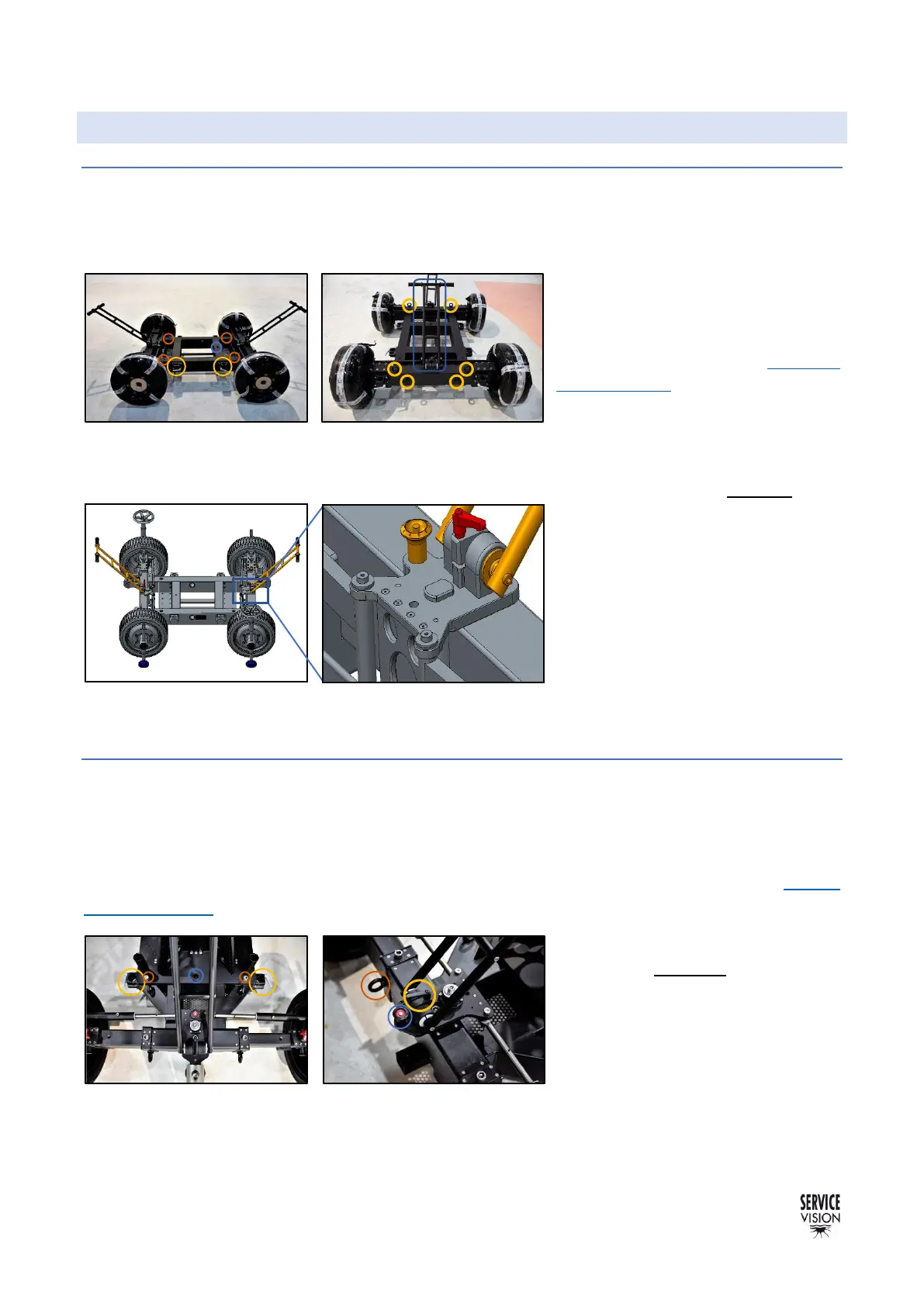
The dolly is the base of the crane, it can be pushed with 48mm or 50mm Aluminum pipes attached
into the supports by tightening the white knobs in the supports for pushing bars. These supports can
also be used as a storage point for the Leveling Jacks of the dolly. There are 8 supports for pushing
bars.
The threads in the dolly and the
guiding pin are used to attach the
column to the dolly. In the chapter 9
Documentation there is a drawing with
the dimensions of this attachment.
There are 8 strap rings to hold the
arm. This strap rings are just to hold
the arm from the dolly, DO NOT lift the
whole crane from here.
The Scorpio 45’ has a dolly with 2
independent steering handles and
pneumatic wheels that allow the
movement of the crane through tight
corners. The steering handles can be
locked introducing the locking pin
(D12x25mm) in the locking position.
2.1.2 38’ DOLLY BASE
The dolly in the 38’ model is slightly different than the 45’. It has 4 supports to attach 48mm or 50mm
pushing bars and two independent steering handles to maneuver the crane. The steering handles
can be locked introducing the locking pin (D12x25mm) in the locking position.
The threads in the dolly and the guiding pin are used to attach the column to the dolly. In the chapter
9 Documentation there is a drawing with the dimensions of this attachment.
There are 8 strap rings to hold the
arm. These CANNOT be used to lift
the crane from here.