SCORPIO 38’ - 45’ - MAINTENANCE & SERVICE - Driver adjustment
Version 1.02 May 27, 2022
76
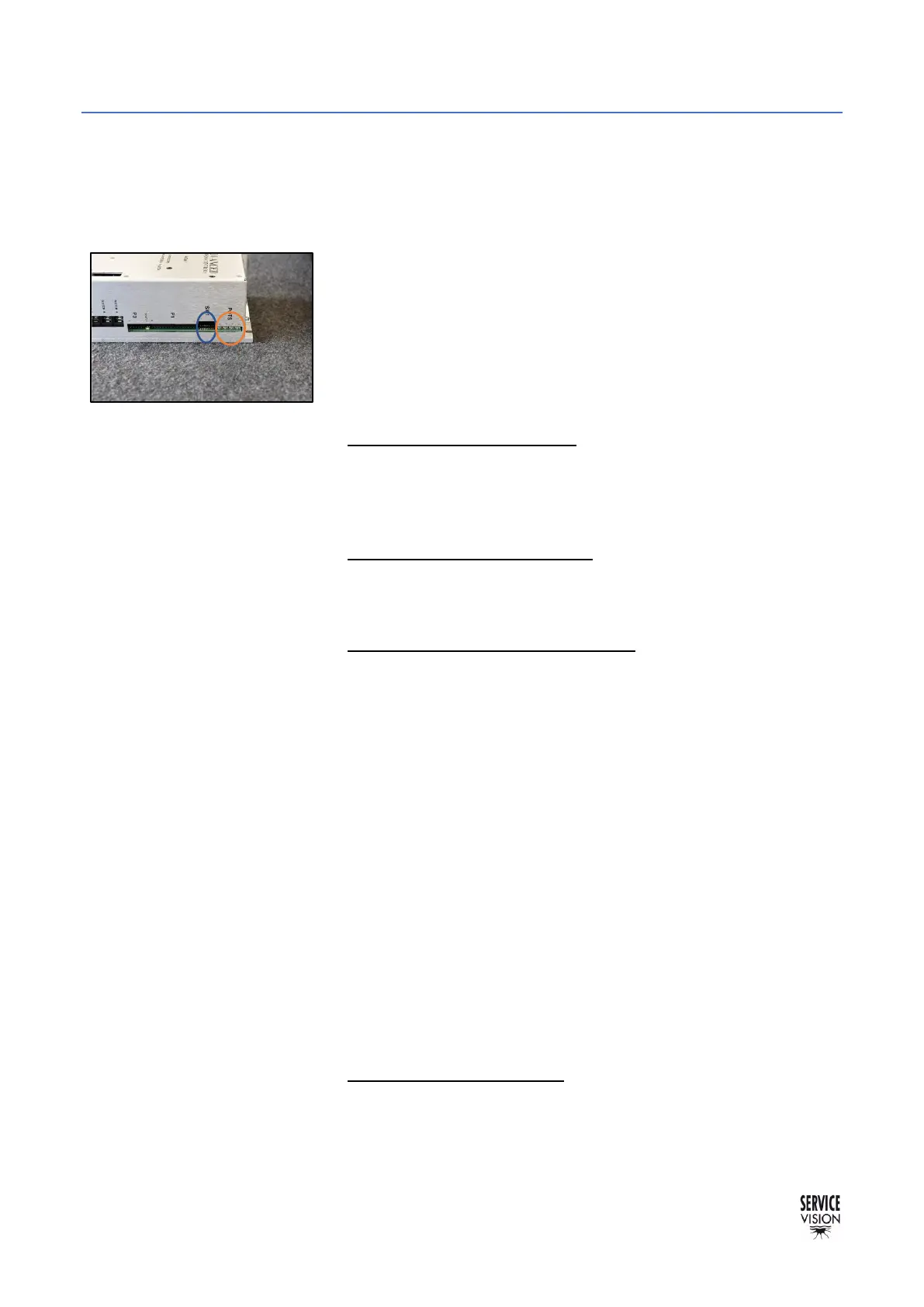
6.5.2 CWE DRIVER
Note this driver in controlling two different motors, the motor of the Dynamic Counterweights System
(CWE) and the motor of the column. Therefore, we will adjust potentiometer 1, 2 for the motor of the
CWE only, the potentiometer 3 for speed will be for the motor of the column and potentiometer number
4 does not need to be adjusted since it’s preset by the factory.
The correct DIP SWITCH address for the motor driver of the arm
and for the motor driver of the CWE and COLUMN is the same:
Switches 3/4/5 and 8 in ON position, rest in OFF position.
Be sure the new driver has the same address before replacing it.
Once the new driver is connected, start the crane, and find the
magnetic limits of the crane. When the main screen is shown, the
driver can be adjusted.
• Potentiometer 1 Loop Gain: Turn the potentiometer number 1
CLOCKWISE until hearing a “buzz” noise. Turn
COUNTERCLOCKWISE now until the “buzz” noise stops. And
from this exact point, keep turning COUNTERCLOCKWISE for 3
turns more and stop. Leave it like this.
• Potentiometer 2 Current Limit: We want this always giving the
maximum current. Turn the potentiometer number 2 CLOCKWISE
until hearing a “click” noise or during 14 full turns CLOCKWISE to
reach its maximum.
• Potentiometer 3 Ref in Gain / SPEED: Change the mode selector
to COLUMN MODE on the commuter on the electronics to set the
crane to work on the column motor. We set speed of the column
motor ONLY, we do not adjust speed on the motor of the Dynamic
Counterweight System.
Using a multimeter at 200VCC check the COLUMN/STANDARD
MODE commuter. Place the red/positive cable to the pin number
2 (in some crane it might be number 3) and the black/negative
cable to pin number 6 of the commuter (in some crane it might be
number 7 instead of 6) see chapter 10 Documentation to find the
driver output.
Now set the speed potentiometer of the hand command to
Maximum speed.
While pushing the rocker in one direction on the hand command,
turn clockwise or counterclockwise to adjust it to +-125VCC.
The values of 125VCC are guideline value, so it might be 124 or
126VCC, what is important is that both values have to be the same
(W in negative and T in positive). We want equal speed when
rising and when lowering down the telescopic column.
• Potentiometer 4 OFFSET: Since this driver is controlling two
different motors, we cannot adjust this parameter. The offset
parameter for the motors will be adjusted from factory.