SCORPIO 38’ - 45’ - MAINTENANCE & SERVICE - Driver adjustment
Version 1.02 May 27, 2022
SERVICEVISION BIS SL
Ríos Rosas, 20 · 08940 CORNELLA DE LLOBREGAT (Barcelona) Spain · Tel. 34 93 223 86 30 · Fax 34 93 223 86 31 77
comercial@servicevision.es · www.servicevision.es
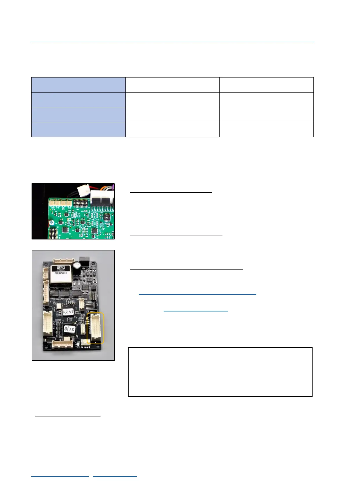
6.5.3 LEVELING HEAD DRIVER
There are different DIP switches on the PCB board, verify the configuration of those DIP switches
with the following table for the LH driver:
Once this is verified, start the crane, and find the magnetic limits of the crane. When the main screen
is shown, the driver can be adjusted.
There are 4 potentiometers in the connectors side. These potentiometers adjust different parameters
of the behavior of the motor and there is no mechanical limit on the numbers of turns they can do.
• Potentiometer 1 Loop Gain: Turn the potentiometer number 1
CLOCKWISE until hearing a “coupling” noise from the motor.
From this point, turn counterclockwise now until the “buzz” noise
stops. And from this exact point, keep turning counterclockwise for
1,5 turns more and stop. Try to be as accurate as possible.
• Potentiometer 2 Current Limit: Always needs to be giving the
maximum current. Turn the potentiometer number 2 CLOCKWISE
until hearing a “click” noise or during 15 full turns CLOCKWISE to
reach its maximum.
• Potentiometer 3 Ref in Gain / SPEED: To adjust the speed it is
mandatory to DISENGAGE the motor of the crane. Switch off the
Electronic Box and remove the belt for the leveling head as seen
in Chapter 2.7.1 Inside the leveling head. Then change the
SERVO I Switch SAd1 direction to MOTOR FREEWHEEL (1,2,3,4
ON) (check documentation chapter). Switch on the Electronic Box
again and turn the potentiometer clockwise 15 times then turn
counterclockwise slowly until the noise of the motor changes.
Power off the Electronic Box and set the SERVO DIP switch 1 as
it was (2,3,5 ON).
• Potentiometer 4 Offset: With the crane started and the mechanics disengaged, remove the DRIVER
connector in the Servo I board, checking if there is any movement in the motor. If so, turn the
potentiometer clockwise or counterclockwise until the movement disappears. Connect the DRIVER
connector of the Servo I board again and engage the motor to the mechanics again with the belt.