-
PC-1600
tained media.
3) Type the command 'LOAD"X:CE·1600F'" and push
the/ENTERlkey.
4) When the prompt symbol appears, remove the test
program stored disk and turn off the PC-1600.
5) Disconnect the test installation CE-1600F from the
CE-1600P.
6) Connect the CE-1600F to be tested with the CE-1600P.
7) Turn on the PC-1600.
8) Type the command 'R.(RUN)', then push the/ENTERI
key.
9) When the prompt is issued for setting of the media,
insert the test media with the side A face up,
10) Push the IENTER [kev. If other key is pushed, the test
resumes from 8).
11) After continuous test of test items, 1 thru 4, "OK"
is displayed when the test has been successful. If not
successful, the error is indicated on the display and the
printer.
12) After successful ending of test items, 1 thru 4, remove
the test media and set the side B of the media whose
write protect tab is set to WP.
13) Push thelENTER/key now to check the function of the
write protect switch. If it has been successful, the
description is printed and the test terminates.
141 During this write protect test period, measure the +5VC
check point of the interface board with the dc voltmeter
to check that it is within a range of 4.5VDC to 5.5VDC
(5V±0.5V).
7-5. Write protect test
This test is conducted to check proper functioning of the
write protect of the floppy disk drive .
• Test description
• Check class 05 (CHECK 05)
Insertion of the media is checked after the motor has
turned on and functioning of the write protect is
checked. That is, it checks that it is the media that
write protected.
• Check items
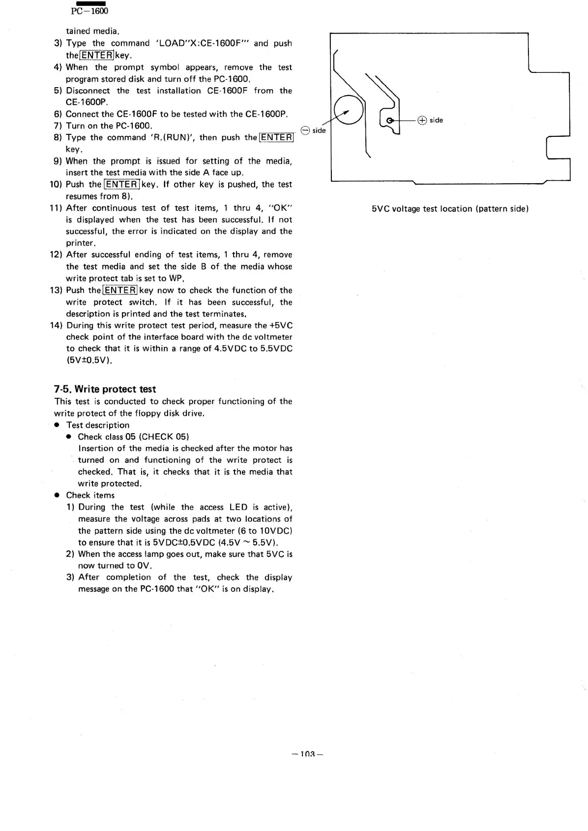
1) During the test (while the access LED is active},
measure the voltage across pads at two locations of
the pattern side using the dc voltmeter (6 to 10VDC)
to ensure that it is 5VDC±0.5VDC (4.5V ~ 5.5V).
2) When the access lamp goes out, make sure that 5VC is
now turned to OV.
3) After completion of the test, check the display
message on the PC·1600 that "OK" is on display.
G;l
side
5VC voltage test location (pattern side)
-10::\-