-
PC-1600
5-2. Chip select signal
(1) CSOOl
This signal must be low to accessthe memory space in
0000H-7FFFH of bank O. The signal is also an input
to the CS line of the ROM.
(2) CS123
This signal must be low to access the memory space
of 8000H-BFFFH of bank 6. The remaining 16KB
area of the second half is for the LH·5803 control
ROM. This signal is also an Input to the CS line of
the ROM.
The ROM (64KB) selected by CSOOl or CS123 is
cleared when a high signal is given to the INH line
which is connected to the system bus and slot (pulied
down to low within the main unit).
(3) CS24
This signal must be low to accessany one of the 16KB
spaces.
(a) For accessing of bank 3 of the memory space in
4000H -7FFFH.
• CS24 is an input to the CS line of 256K bits
ROM.
• A15 is connected to OE of the ROM.
• This 16KB space is further banked by another
port signal to compose a 32 KB area.
(4) RAM3
This signal must be high to accessthe memory space
in COOOH-FFFFH of bank O. This signal is connected
to CE2 of the two 8KB RAMs. A 13 is used to
determine wh ich RAM is to be selected.
OOOOH
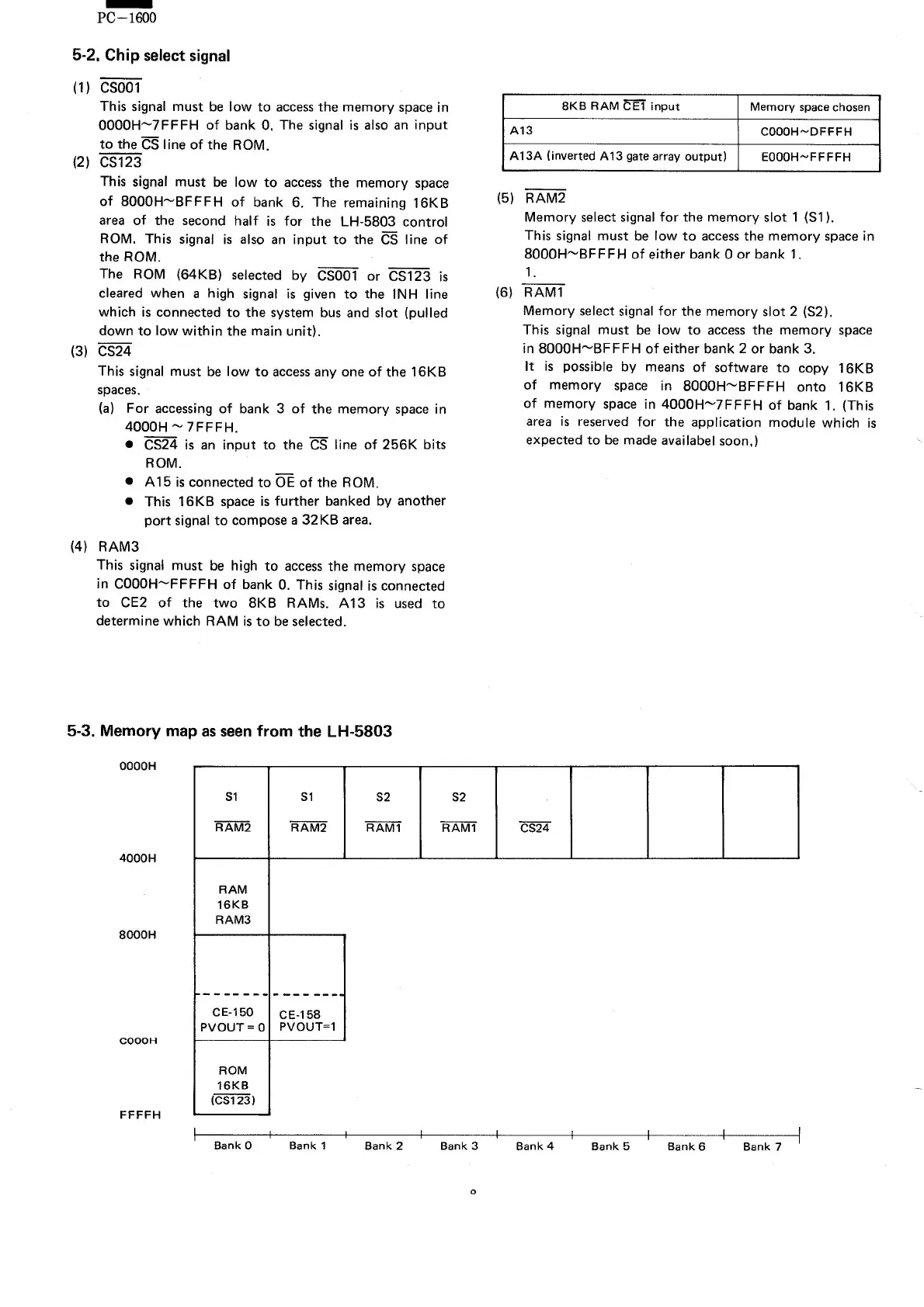
5-3. Memory map as seen from the LH-5803
4000H
8000H
COOOH
FFFFH
8KB RAM CEl input
Memory spacechosen
A13
COOOH~DFFFH
A13A (inverted A13 gate array output)
EOOOH~FFFFH
(5) RAM2
Memory select signal for the memory slot 1 (Sl).
This signal must be low to accessthe memory space in
8000H-BFFFH of either bank 0 or bank 1.
1.
(6) RAMl
Memory select signal for the memory slot 2 (S2).
This signal must be low to access the memory space
in 8000H-BF FFH of either bank 2 or bank 3.
It is possible by means of software to copy 16KB
of memory space in 8000H-BFFFH onto 16KB
of memory space in 4000H-7FFFH of bank 1. (This
area is reserved for the application module which is
expected to be made availabel soon,)
Sl Sl
S2 S2
RAM2
RAM2 RAMl
RAMl CS24
RAM
16KB
RAM3
-------
-------
CE·150
CE·158
PVOUT= 0
PVOUT=1
ROM
16KB
(CS123)
Bank
0
Bank 2
Bank
7
Sank 1
Sank 3 Bank 4
Bank 5 Bank 6
o