4-1. Relation of the main CPU-1 to the main
CPU·2
Since two CPUs are linked together, the bus line of one
CPU is on the sytem bus; the other CPU bus is
kept
in the
floating state.
Shown in the following table are the bus signals of the two
CPUs in connection.
SC7852 signal name
Z-80 signal name LH-5803 signal name
I
A15 - AO A15 - AO
A15 - AO
OB7 - OBO
07 - 00 07 - 00
MREG
Opposite polarity
MEO
of MREG
10RG
Opposite polarity
ME1
of IORG
RO
RO
00*
WR
WR
R/W
* The
00
outpur
of the LH·5803 is connected to
RD
of
the SC7852 via the gate array (LR38041).
The operating CPU is indicated by the ELH signal.
ELH = Low: LH·5803
ELH
=
High: Z·80
RSTIN
ELH
RSTO
LH·5B03
LH·5803 Z-80
Z·80
LHWAIT
---+---____j
Z·80
instruction
HA LT
OUT(38H)A
LH·5803
instruction
HALT
OUT(38H), A
STA #A038H. A
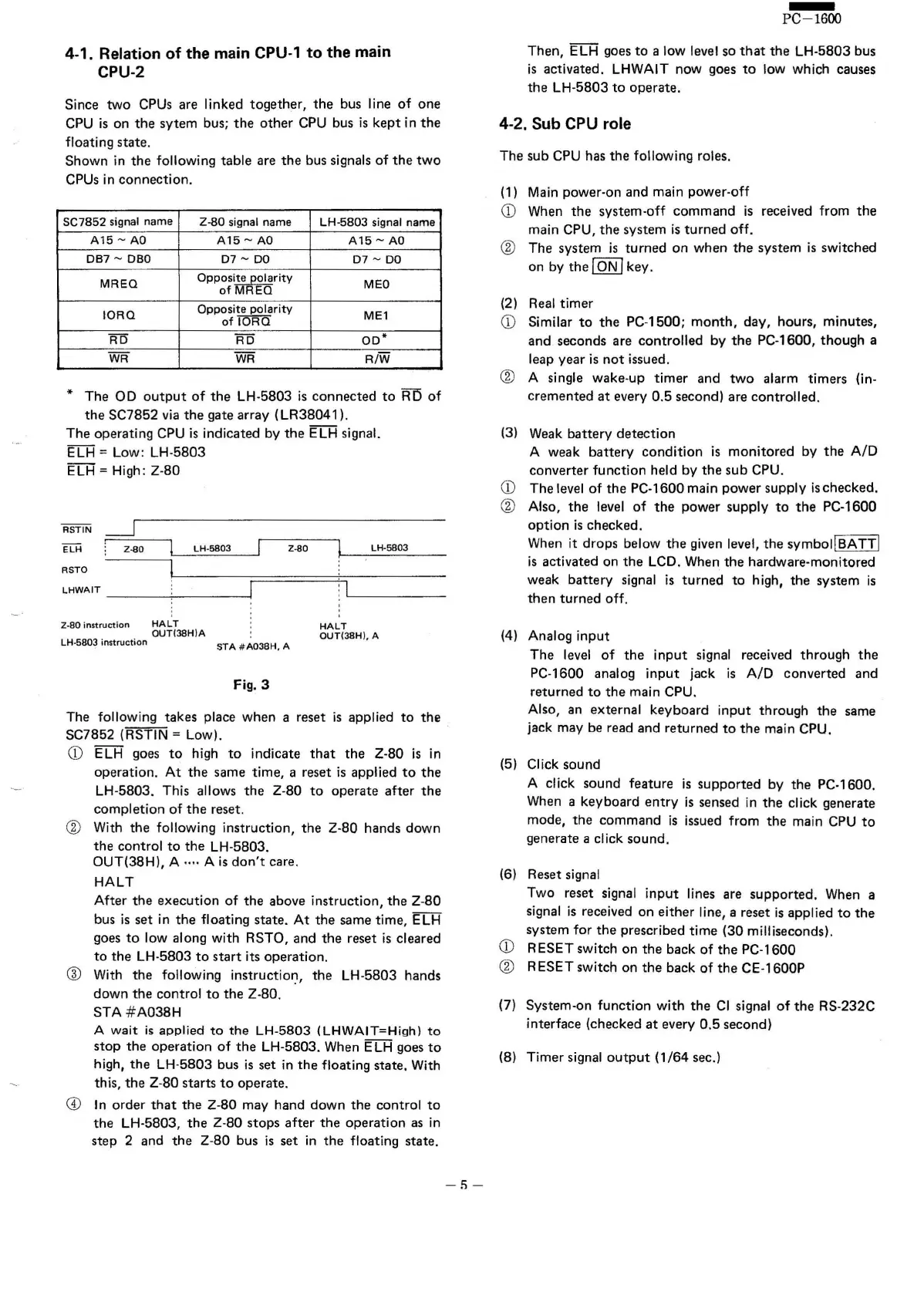
Fig.3
The following takes place when areset is applied to the
SC7852 (RSTIN
=
l.ow).
CD
ELH goes to high to indicate that the Z-80 is in
operation. At the same time, areset is applied to the
LH-5803. This allows the Z-80 to operate after the
completion of the reset.
® With the followinq instruction, the Z·80 hands down
the control to the LH-5803.
OUT(38Hl, A .... Ais don't care.
HALT
After the execution of the above instruction, the Z-80
bus is set in the floating state. At the same time, ELH
goes to low along with RSTO, and the reset is cleared
to the LH-5803 to start its operation.
® With the following instruction, the LH-5803 hands
down the control to the Z-80.
STA #A038H
A wait is applied to the LH-5803 (LHWAIT=High) to
stop the operation of the LH-5803. When ELH goes to
high, the LH·5803 bus is set in the floating state, With
this, the Z·80 starts to operate.
CD
In order that the Z-80 may hand down the control to
the LH·5803, the Z-80 stops after the operation as in
step 2 and the Z-80 bus is set in the floating state.
-!)-
-
PC-1600
Then, ELH goes to a low level so that the LH-5803 bus
is activated. LHWAIT now goes to low which causes
the LH-5803 to operate.
4-2. Sub CPU role
The sub CPU has the following roles.
(1) Main power-on and main power-off
CD
When the system-off command is received from the
main CPU, the system is turned off.
® The system is turned on when the system is switched
on by the
ION I
key.
(2) Real timer
CD
Similar to the PC-1500; month, day, hours, minutes,
and seconds are controlled by the PC-1600, though a
leap year is not issued.
® A single wake-up timer and two alarm timers (in-
cremented at every 0.5 second) are controlled.
(3)
Weak battery detection
A weak battery condition is monitored by the A/D
converter function held by the sub CPU.
CD
The level of the PC·1600 main power supply ischecked.
® Also, the level of the power supply to the PC-1600
option
is checked.
When it drops below the given level, the symbol!SATT!
is activated on the LCD. When the hardware-monitored
weak battery signal is turned to high, the system is
then turned off.
(4)
Analog
input
The level of the input signal received through the
PC-1600 analog input jack is A/D converted and
returned to the main CPU.
Also, an external keyboard input through the same
jack may be read and returned to the main CPU.
(5) Click sound
A click sound feature is supported by the PC-1600.
When a keyboard entry is sensed in the dick generate
mode, the command is issued from the main CPU to
generate a click sound.
(6) Reset signal
Two reset signal Input
tines
are supported. When a
signal is received on either line, areset is applied to the
system for the prescribed time (30 milliseconds).
CD
RESET switch on the back of the PC-1600
® RESET switch on the back of the CE·1600P
(7) System-on function with the CI signal of the RS-232C
interface (checked at every 0.5 second)
(8) Timer signal outout (1/64 sec.)