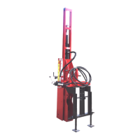
2. Install hydraulic base plate (F2) on three-
point hitch weldment (K1), as shown.
Install carriage bolts, washers,
lockwashers, and nuts removed in Step 1.
Center the base plate on the three-point
hitch and tighten the hardware securely.
(F2) Hydraulic Base Plate. (K1) Three-Point Hitch
Weldment.
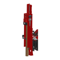
3. Locate tilt cylinders (F3, F4). Install four
hose assemblies (H5) using paste-type
thread sealant (T12) on the fittings. Tighten
the hose fittings securely.
(F3) Forward Tilt Hydraulic Cylinder. (F4) Side Tilt
Hydraulic Cylinder. (H5) Hydraulic Cylinder Hose
Assembly.
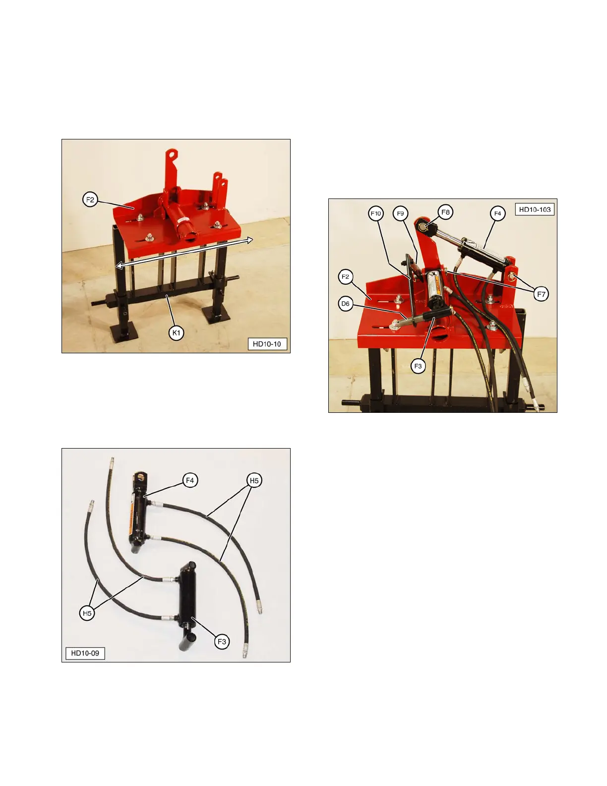
4. Install hydraulic cylinders (F3, F4) on
hydraulic base plate (F2), along with safety
lever (F9, F10), as shown. Secure with
Lynch pins (included).
NOTE: Side tilt cylinder (F4) is secured with
cylinder mounting pins (F7, F8). Forward tilt
cylinder (F3) and safety lever (F9, F10) are
secured with cylinder mounting pin (F7) and
channel mounting pin (D6).
(D6) Channel Mounting Pin. (F2) Hydraulic Base Plate.
(F3) Forward Tilt Hydraulic Cylinder. (F4) Side Tilt
Hydraulic Cylinder. (F7) Long Cylinder Mounting Pin.
(F8) Short Cylinder Mounting Pin. (F9, F10) Safety Lever.
11