The main carriage channel
assembly is tall and heavy. To
avoid tip over, resulting in serious
injury or death, leave the overhead
lifting device attached to the main carriage
channel while assembling components.
5. Install the hydraulic base plate on the short
channel bracket.
a. Get assistance to position hydraulic
base plate (F2) in front of hydraulic
short channel bracket (D2).
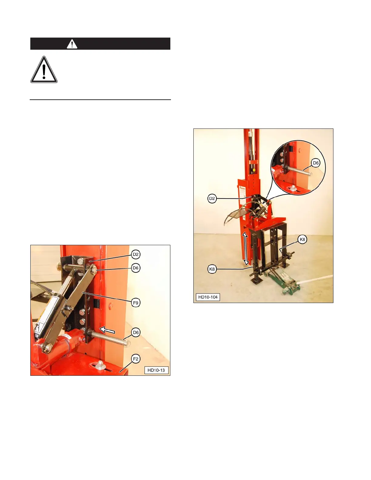
b. Manually extend forward tilt cylinder
and install upper channel mounting pin
(D6) through short channel bracket
(D2) and safety lever (F9). Make sure
safety lever link (F9) is installed on
upper channel mounting pin (D6), as
shown. Secure with Lynch pins
(included).
c. Start lower channel mounting pin (D6)
in lower short channel bracket, as
shown.
(D2) Short Channel Bracket. (D6) Short Channel Bracket
Mounting Pin. (F2) Hydraulic Base Plate. (F9) Safety
Lever Link.
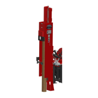
d. Use a suitable floor jack to support the
three-point hitch weldment.
e. Loosen stabilizer leg lock bolts (K8),
and adjust floor jack up or down to
align base plate pivot pin hole with
short channel (D2) lower mounting
hole.
f. Install lower channel mounting pin (D6)
and secure with Lynch pins. Tighten
the two stabilizer leg lock bolts and
remove the floor jack.
(D2) Hydraulic Short Channel Bracket.
(K8) Stabilizer Leg Lock Bolts.