141
2. CONTROL VALVE ASSEMBLY
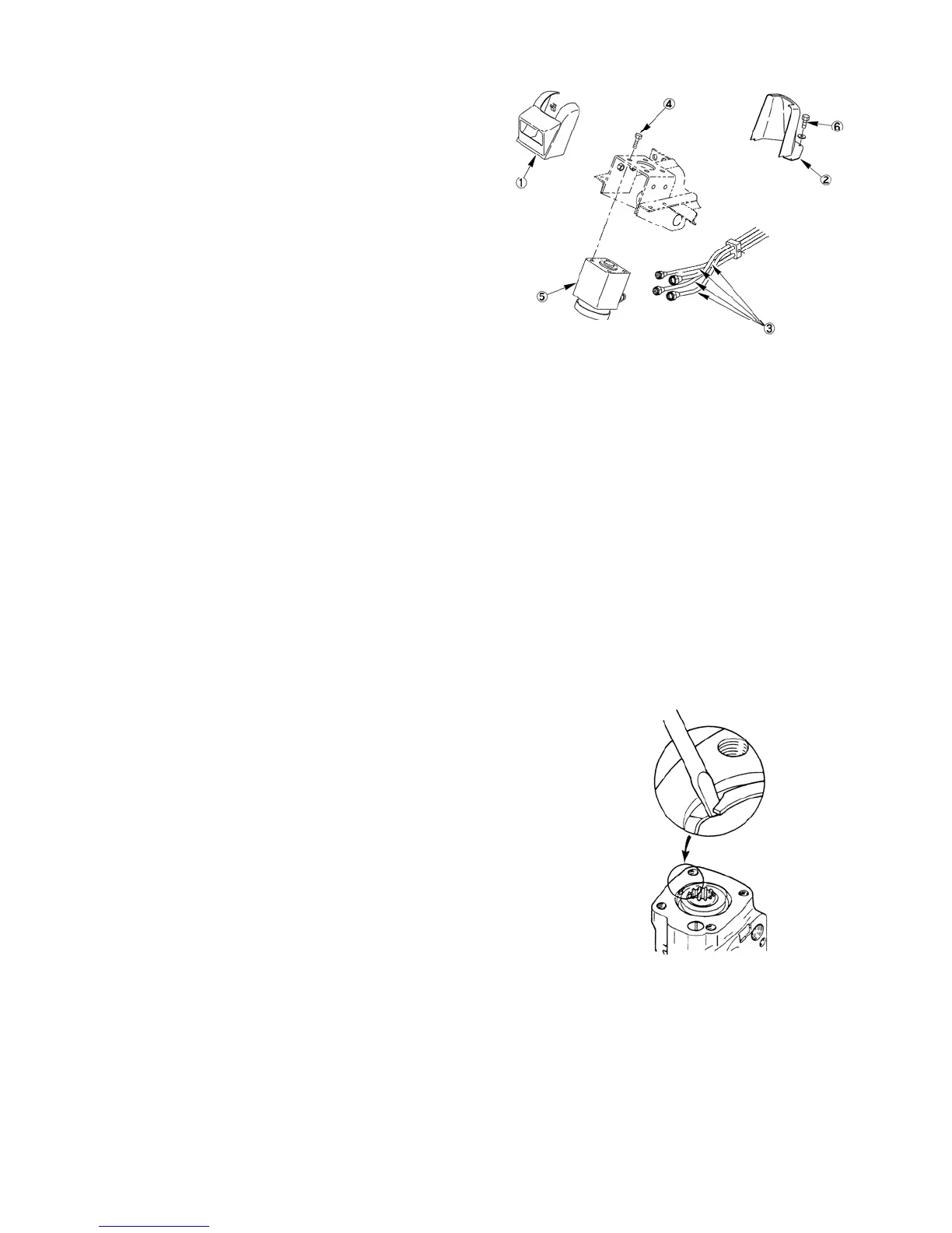
1) Removal
1. Disconnect the negative battery cable from the
battery post.
2. Pull the light musk ① to front ward and
remove the bolts ⑥ and lower cover ② from
the floor.
3. Disconnect the four oil pipes ③ from the
control valve.
4. Remove the four bolts ④ and control valve ⑤
from the frame.
505X
2) Disassembly
Reference – Figure 507X.
1. Place the control valve upside down in a vise, and remove the retaining bolts (22) and check valve retainer bolt
(23).
NOTE: Use soft metal jaws on the vise and apply only enough pressure to support the valve assembly. Do not
over tighten or the valve body may become distorted and permanently damaged.
2. Remove the end cap (21), seals (20) and O-Ring (16).
3. Remove the Gerotor gear pump (19) and O-Ring (16).
NOTE: The inner rotor separates easily from the outer pump body rotor. Use care in handling to prevent
damage to these components.
4. Remove the second large O-Ring (16).
5. Remove the drive shaft (18), spacer plate (17) and third large O-Ring (16).
6. Remove the check ball (24).
7. Remove the retaining ring (2).
NOTE: Remove the valve from the vise and
place on a clean lint-free shop towel.
Use care in handling the valve parts
so as not to mar or damage the
precision finishes.
506X
8. Rotate the spool and sleeve to position the pin horizontally. Gently push on the bottom end of the spool and
sleeve forcing the gland (3) out of the valve body.
9. Separate the seals (1) and (5) from the gland (3).
10. Remove the thrust bearing (7) and two bearing races (6).
11. Remove the spool and sleeve as an assembly (13), (14) and (15).
12. Remove the pin (14).