Home
Shini
Industrial Equipment
SAL-UGP Series
Shini SAL-UGP Series User Manual
4
of 1
of 1 rating
61 pages
Give review
Manual
Specs
To Next Page
To Next Page
To Previous Page
To Previous Page
Loading...
10(61)
1
.
3
T
ec
h
n
i
c
a
l
Sp
e
c
if
i
c
a
ti
o
ns
1
.
3
.
1
T
e
c
hn
i
c
a
l
S
pe
c
i
f
i
c
a
t
i
o
n
s
(M
a
i
n
U
n
i
t
)
P
i
c
t
u
r
e
1
-1
:
SAL
-
1
H
P
/
2
H
P
-U
GP
P
i
c
t
u
r
e
1
-2
:
SAL
-
3
.
5
H
P/5
H
P
-U
GP
P
i
c
t
u
r
e
1
-3
:
SAL
-
7
.
5
H
P/10
H
P
-U
GP
1
.
3
.
2
T
h
e
O
u
t
e
r
Dim
en
s
i
o
n
o
f
H
o
p
pe
r
9
11
Table of Contents
Default Chapter
3
Table of Contents
3
1 General Description
7
Coding Principle
8
Feature
8
Technical Specifications
10
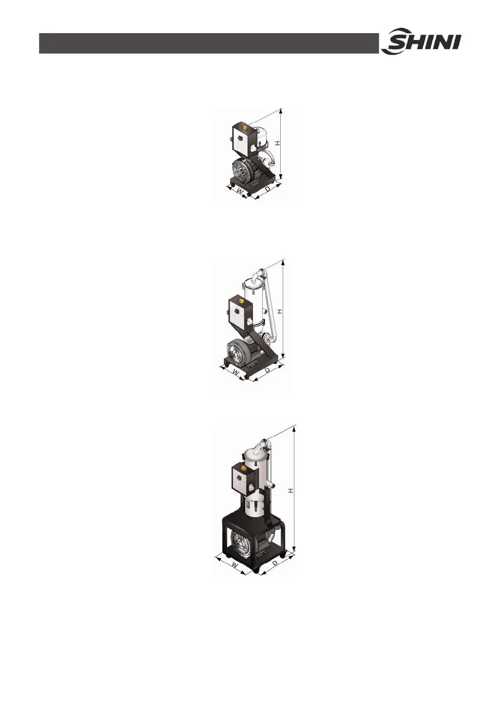
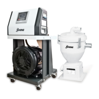
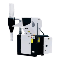
Technical Specifications (Main Unit)
10
The Outer Dimension of Hopper
10
Picture 1-1:SAL-1HP/2HP-UGP
10
Picture 1-2:SAL-3.5HP/5HP-UGP
10
Picture 1-3:SAL-7.5HP/10HP-UGP
10
The Installation Dimension of Hopper
11
Picture 1-4:SHR-P-12U
11
Picture 1-5:SHR-P-30U~SHR-P-90U
11
Picture 1-6:SHR-P-30U~SHR-P-90U
11
Specifications
12
Safety Regulations
14
Safety Signs and Labels
14
Signs and Labels
14
Exemption Clause
14
2 Structure Characteristics and Working Principle
16
Main Functions
16
SAL-UGP Working Principle
16
Picture 2-1:SAL-UGP Working Principle
16
Assembly Drawing
18
Assembly Drawing (SAL-1/2HP-UGP)
18
Picture 2-2:Assembly Drawing (SAL-1/2HP-UGP)
18
Parts List (SAL-1HP/2HP-UGP)
19
Assembly Drawing (SAL-3.5HP/5HP-UGP)
20
Picture 2-3:Assembly Drawing (SAL-3.5HP/5HP-UGP)
20
Parts List (SAL-3.5HP/5HP-UGP)
21
Assembly Drawing (SAL-7.5HP/10HP-UGP)
22
Picture 2-4:Assembly Drawing (SAL-7.5HP/10HP-UGP)
22
Parts List (SAL-7.5HP/10HP/15HP-UG)
23
Assembly Drawing of Storage Hopper with Plate Filter
24
Picture 2-5:Assembly Drawing of Storage Hopper with Plate Filter
24
Parts List of Storage Hopper with Plate Filter
25
Assembly Drawing of the Storage Hopper with Bag Filter
26
Picture 2-6:Assembly Drawing of the Storage Hopper with Bag Filter
26
Parts List of the Storage Hopper with Bag Filter
27
Electrical Diagram
28
Main Circuit (400V)
28
Picture 2-7:Main Circuit 1 (400V)
28
Picture 2-8:Main Circuit 2 (400V)
29
Electrical Components Layout (400V)
30
Picture 2-9:Electrical Components Layout (400V)
30
Electrical Components List (400V)
31
Main Circuit (230V)
37
Picture 2-10:Main Circuit 1 (230V)
37
Picture 2-11:Main Circuit 2 (230V)
38
Electrical Components Layout (230V)
39
Picture 2-12:Electrical Components Layout (230V)
39
Electrical Components List (230V)
40
Description of Electrical Components
46
Magnetic Proximity Switch
46
Main Electrical Components Description
46
Picture 2-13:Magnetic Proximity Switch
46
Picture 2-14:Overload Relay
46
3 Installation and Debugging
48
Installation Steps
48
Power Supply
48
4 Application and Operation
49
Start / Stop of the Machine
49
Keys on the Control Panel
49
Parameter Setting
49
Enter Basic Setting Mode
49
Picture 4-1:Keys on the Control Panel
49
Modify a Parameter
50
Finish Parameter Setting
50
Basic Parameter List
51
Process Setting
51
Enter into Process Setting Mode
51
Modify a Parameter
52
Finish Parameter Setting
52
Process Parameter List
52
Special Process Setting
53
Enter into Special Step Setting Mode
53
Modify a Parameter
53
Finish Parameter Setting
54
Parameter List of Special Process Setting
54
Explanation of Operation Procedures
55
Operation Procedures
55
Alarms
56
5 Trouble-Shooting
58
6 Maintenance and Repair
59
Material Hopper
59
Main Body
59
4
Based on 1 rating
Ask a question
Give review
Questions and Answers:
Need help?
Do you have a question about the Shini SAL-UGP Series and is the answer not in the manual?
Ask a question
Shini SAL-UGP Series Specifications
General
Brand
Shini
Model
SAL-UGP Series
Category
Industrial Equipment
Language
English
Related product manuals
Shini SAL-3.5HP-UGP
61 pages
Shini SAL-10HP-UG
33 pages
Shini SAL-810
33 pages
Shini SAL-800G Series
55 pages
Shini SHD
62 pages
Shini SG-3060 230V
107 pages
Shini SG-23 Series
107 pages