6(61)
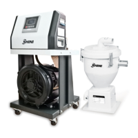
Picture 1-1:SAL-1HP/2HP-UGP.....................................................................10
Picture 1-2:SAL-3.5HP/5HP-UGP..................................................................10
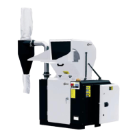
Picture 1-3:SAL-7.5HP/10HP-UGP................................................................10
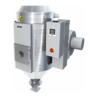
Picture 1-4:SHR-P-12U..................................................................................11
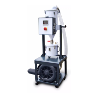
Picture 1-5:SHR-P-30U~SHR-P-90U.............................................................11
Picture 1-6:SHR-P-30U~SHR-P-90U.............................................................11
Picture 2-1:SAL-UGP Working Principle........................................................16
Picture 2-2:Assembly Drawing (SAL-1/2HP-UGP).........................................18
Picture 2-3:Assembly Drawing (SAL-3.5HP/5HP-UGP).................................20
Picture 2-4:Assembly Drawing (SAL-7.5HP/10HP-UGP)...............................22
Picture 2-5:Assembly Drawing of Storage Hopper with Plate Filter................24
Picture 2-6:Assembly Drawing of the Storage Hopper with Bag Filter...........26
Picture 2-7:Main Circuit 1 (400V)...................................................................28
Picture 2-8:Main Circuit 2 (400V)...................................................................29
Picture 2-9:Electrical Components Layout (400V)..........................................30
Picture 2-10:Main Circuit 1 (230V).................................................................37
Picture 2-11:Main Circuit 2 (230V).................................................................38
Picture 2-12:Electrical Components Layout (230V)........................................39
Picture 2-13:Magnetic Proximity Switch.........................................................46
Picture 2-14:Overload Relay..........................................................................46
Picture 4-1:Keys on the Control Panel...........................................................49
 Loading...