12 Technical data
12.1 Data sheet
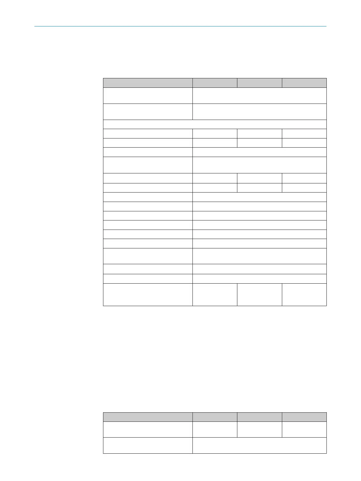
Table 10: General system data
Minimum Typical Maximum
Protective field height, depending on
t
ype
150 mm to 600 mm, 50-mm steps
600 mm to 1500 mm, 150-mm steps
Resolution (detection capability),
dependin
g on type
14 mm or 30 mm
Protective field width
1)
2)
3)
Resolution 14 mm 0 m … 3.6 m 0 m … 4.5 m
Resolution 30 mm 0 m … 3.6 m 0 m … 4.5 m
Protection class
4)
III (IEC 61140)
Enclosure rating IP65 (IEC 60529)
IP67 (IE
C 60529)
Supply voltage U
V
a
t the device
5)
6)
19.2 V 24 V 28.8 V
Residual ripple
7)
± 10%
Synchronization Optical
Type Type 4 (IEC 61496-1)
Category Category 4 (ISO 13849-1)
Performance level
8)
PL e (ISO 13849–1)
Safety integrity level
8)
SIL3 (IEC 61508)
SIL claim limit
8)
SILCL3 (IEC 62061)
PFHd (mean probability of one dan‐
g
erous failure per hour)
3.7 × 10
-9
T
M
(mis
sion time) 20 years (ISO 13849-1)
Safe status when a fault occurs At least one OSSD is in the OFF state.
Power-up delay of sender and
r
eceiver after supply voltage is
applied
2 s
1)
If the protective fields are very wide, there is a possibility that all four alignment quality LEDs will not light
up e
ven when alignment is excellent.
2)
The minimum scanning range specifies a range in which a function is guaranteed to operate correctly
and safely under industrial conditions. A sufficient level of signal reserve to ensure very high availability is
included in the calculation.
3)
The typical scanning range specifies a range in which the safety light curtain operates correctly and safely
under industrial conditions. The level of signal reserve is enough to ensure high availability.
4)
SELV/PELV safety extra-low voltage.
5)
The external voltage supply must be capable of bridging a brief power failure of 20 ms as specified in
IEC 60204-1. Suitable power supply units are available as accessories from SICK.
6)
A fuse rated maximum 2 A shall be installed in the isolated 24 V DC power supply circuit to the device in
order to limit the available current.
7)
Within the limits of U
V
.
8)
For more detailed information on the exact configuration of your machine, please contact your relevant
SIC
K subsidiary.
Table 11: Technical data for sender
Minimum Typical Maximum
Wavelength of sender Near-infrared
(NIR
), invisible
Weight Depending on the protective field height, see "T
able of
weights", page 64
TECHNICAL DATA 12
8025644/19Z2/2021-03-09 | SICK O P E R A T I N G I N S T R U C T I O N S | C4-RD
61
Subject to change without notice