NOTICE
T
he AR60 optional laser alignment aid can be used from a protective field height of
250 mm.
Mounting method
T
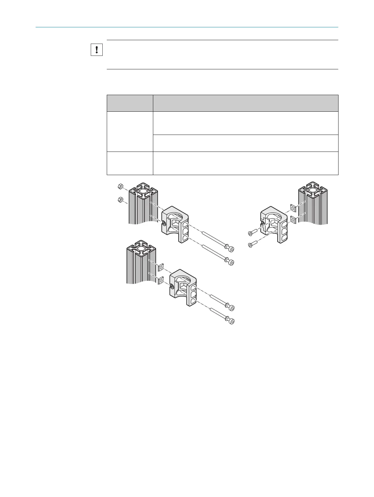
able 5: Lateral and rear mounting of the Compact FlexFix bracket on a machine or profile frame
Mounting
me
thod
Description
On the side With the M5 screw through the Compact FlexFix bracket on the machine or
profile frame. A screw nut or threaded hole is required on the machine or
profile frame (!).
With the M5 screw through the Compact FlexFix bracket on the profile
fr
ame. 2 sliding nuts are required on the profile frame (").
On the back With the M5 countersunk screw through the Compact FlexFix bracket on the
mac
hine or profile frame. A screw nut or threaded hole is required on the
machine or profile frame (§).
Figure 23: Mount the Compact FlexFix bracket on a profile frame
Approach
1.
After assembling the Compact FlexFix brackets, screw the sender or receiver into
the Compact FlexFix brackets from the front.
2.
Align the sender and receiver. (")
3. Use an M5 screw to secure the position of the sender and receiver in the Compact
FlexFix bracket.
5 MOUN
TING
38
O P E R A T I N G I N S T R U C T I O N S | C4-RD 8025644/19Z2/2021-03-09 | SICK
Subject to change without notice