Minimum Typical Maximum
Housing cross-section 31 mm × 34 mm, plus bracket, see "Dimensional dr
aw‐
ings", page 65
Vibration resistance
4)
5 g, 10 Hz … 55 Hz (IEC 60068-2-6)
Shock resistance
5)
10 g, 16 ms (IEC 60068-2-27)
1)
Maximum permissible conductor resistance must be observed.
2)
The temperature difference between sender and receiver must not exceed 25 K.
3)
The cable belonging to the device incl. the associated connection plug must not be flexibly mounted
under –25 °C
.
4)
Test conditions per axis: 1 octave/minute, amplitude: 0.35 mm, 20 sweeps.
5)
Test conditions per axis: 1,000 shocks.
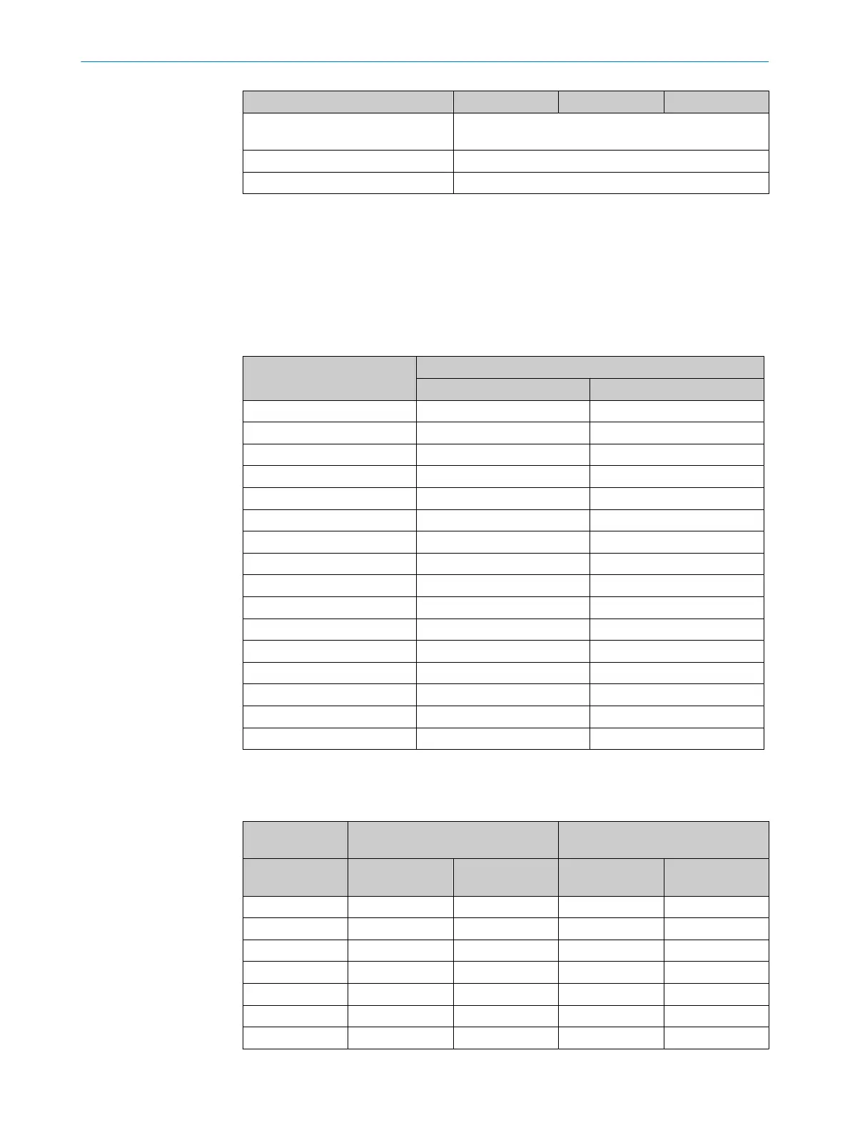
12.2 Response time
Table 15: Response time dependent on the protective field height
Protective field height in mm Response time in ms
Resolution 14 mm Resolution 30 mm
150 10 9
200 10 9
250 10 9
300 11 10
350 11 10
400 11 10
450 12 10
500 12 10
550 12 10
600 13 10
750 13 11
900 14 11
1050 15 11
1200 16 12
1350 17 12
1500 18 13
12.3 Power consumption
Table 16: Power consumption, sender and receiver
Protective field
hei
ght in mm
Typical power consumption of
sender in W
Typical power consumption of
receiver in W
1)
Resolution
14 mm
Resolution
30 mm
Resolution
14 mm
Resolution
30 mm
150 0.84 0.77 1.68 1.54
200 0.88 0.78 1.76 1.57
250 0.92 0.80 1.84 1.60
300 0.96 0.82 1.92 1.63
350 1.00 0.83 2.00 1.66
400 1.04 0.85 2.08 1.70
450 1.08 0.86 2.16 1.73
TECHNICAL DATA 12
8025644/19Z2/2021-03-09 | SICK O P E R A T I N G I N S T R U C T I O N S | C4-RD
63
Subject to change without notice