7.3 Configuration mode
Table 17: Configuration mode
Sender Receiver
Configuration mode is active
•
W
hen resetting the sender
to the factory settings
•
When resetting the receiver
to the factory settings
•
A permissible change to the
external device monitoring
configuration has been dis‐
covered during switch-on
•
The reset pushbutton was
pressed in order to config‐
ure the restart interlock fol‐
lowing switch-on
Display of the configuration
mode
•
Field indicator: Ö Green
•
STATE LED: O Red
•
Field indicator: Ö Green
•
OSSD LED: O Red
o LED of
f. Ö LED flashes. O LED illuminates.
Provided that the device is in configuration mode, you can make further changes to
t
he configuration:
•
Configuring the restart interlock
Stopping configuration mode
b
Br
iefly interrupt the voltage supply, then switch it back on.
7.4 Configuring beam coding
Overview
T
he beam coding “uncoded” allows for particularly short response times.
To protect against interference from systems in close proximity to each other, code 1
and code 2 must be used
The beam coding must be the same for the sender and receiver.
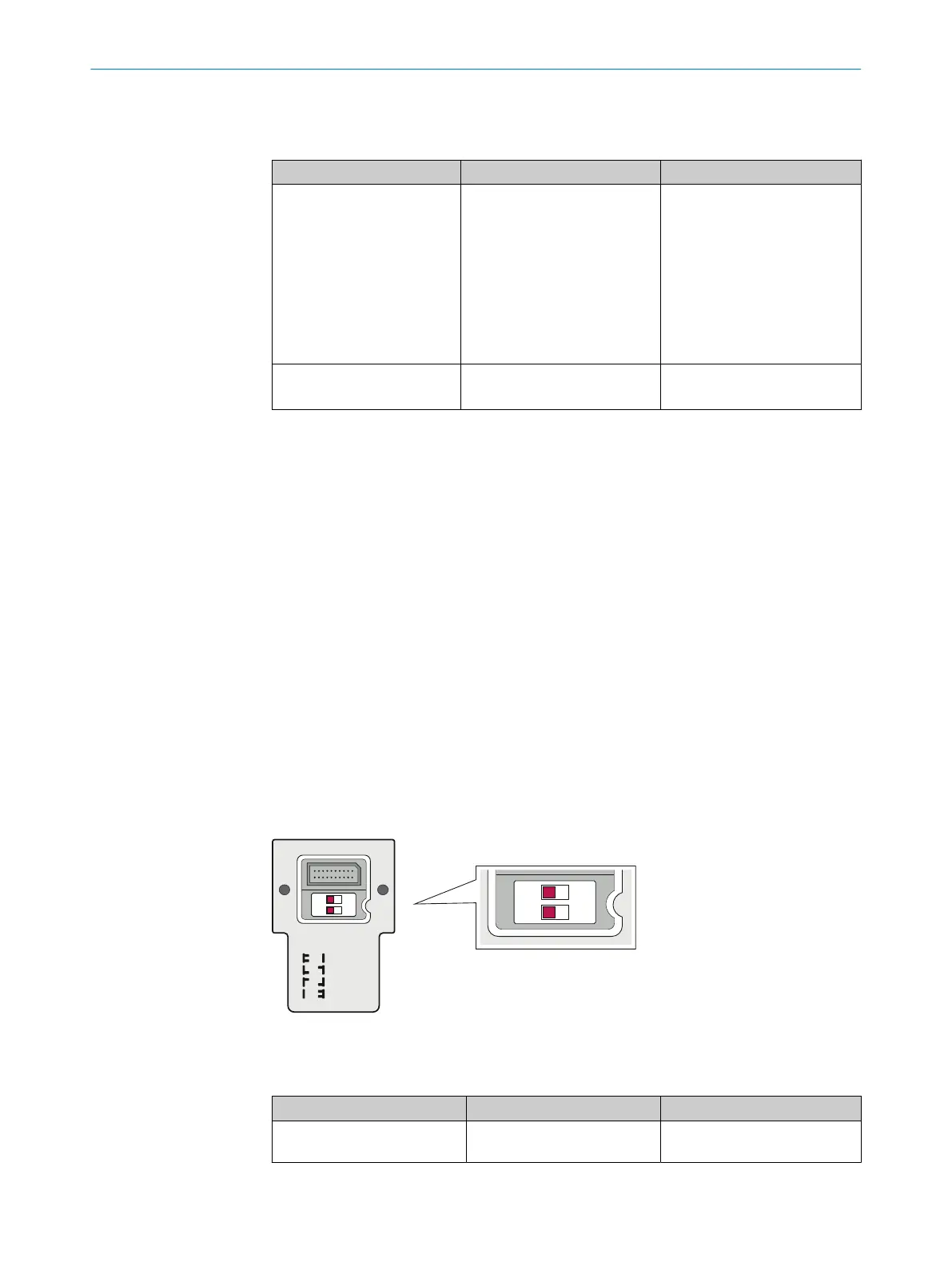
Configuring beam coding
T
he beam coding is configured using 2 DIP switches. The DIP switches are located on
the inside of the system plug.
OFF
uncoded
code 1
code 2
rev.conf.
ON
1
O N
2
Figure 39: Configuring beam coding
T
able 18: DIP switches and beam coding
DIP switch 1 DIP switch 2 Function
Off Off Uncoded (fast response time,
de
livery status)
CONFIGURATION 7
8027140/2021-11-04 | SICK O P E R A T I N G I N S T R U C T I O N S | deTec4
55
Subject to change without notice