Further topics
•
"Int
egration in electrical control", page 30
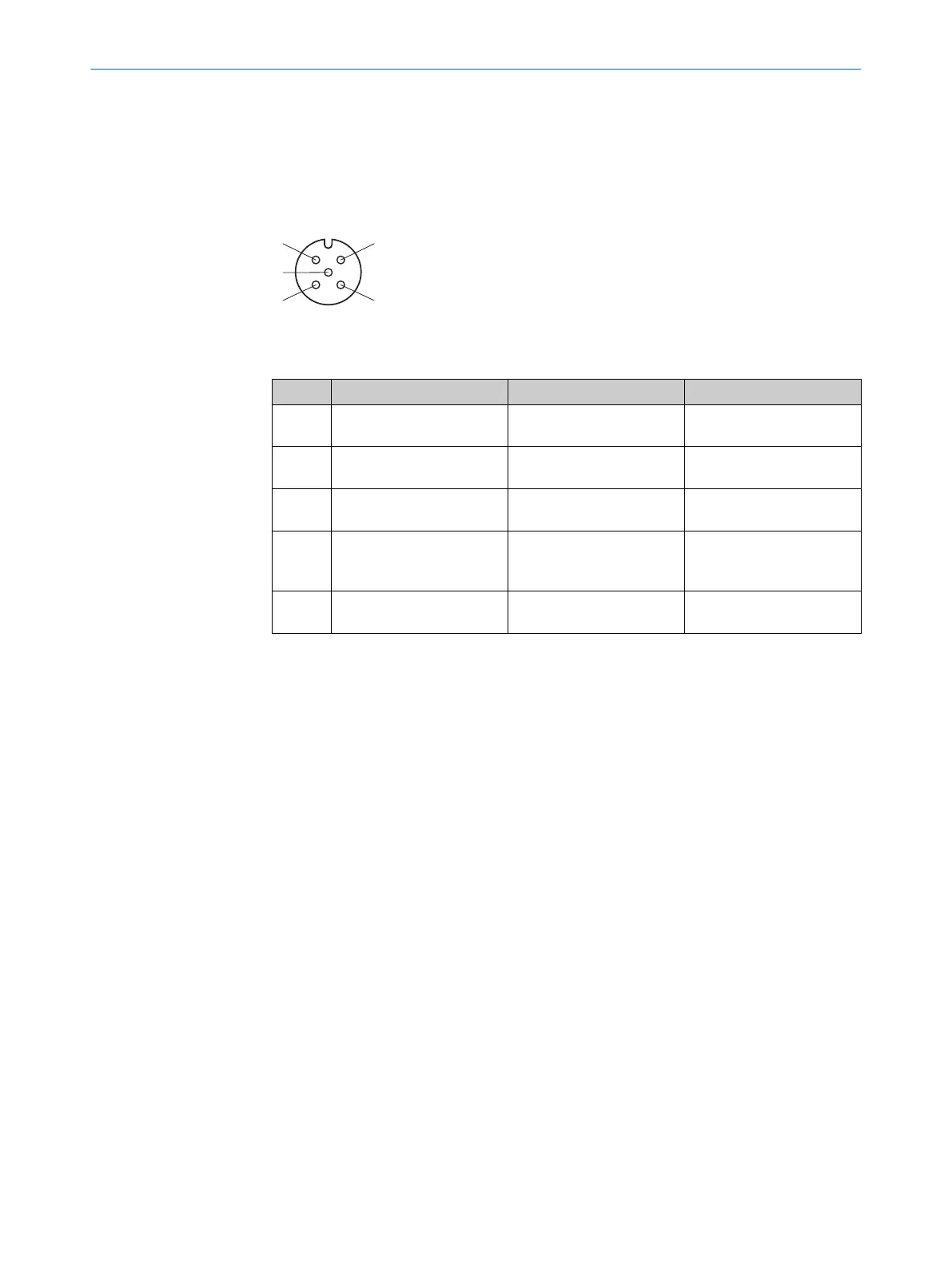
6.4 Extension connection (M12, 5-pin)
Pin assignment at the extension connection
Figure 36: Extension connection (female connector M12, 5-pin)
Table 13: SP1 system plug extension connection pin assignment (M12 female connector, 5-pin)
PIN Wire color
1)
s S
ender r Receiver
1 Brown 24 V Out (voltage supply
out
put)
24 V Out (voltage supply
output)
2 White Not assigned In1
(EDM input)
3 Blue 0 V Out (voltage supply out‐
put)
0 V Out (voltage supply out‐
put)
4 Black Sync-out In2
(R
eset pushbutton input:
RES)
5 Gray MFP2 MFP2
N
ot assigned
1)
Applies to the connecting cables recommended as accessories.
Further topics
•
"Int
egration in electrical control", page 30
6 ELE
CTRICAL INSTALLATION
52
O P E R A T I N G I N S T R U C T I O N S | deTec4 8027140/2021-11-04 | SICK
Subject to change without notice