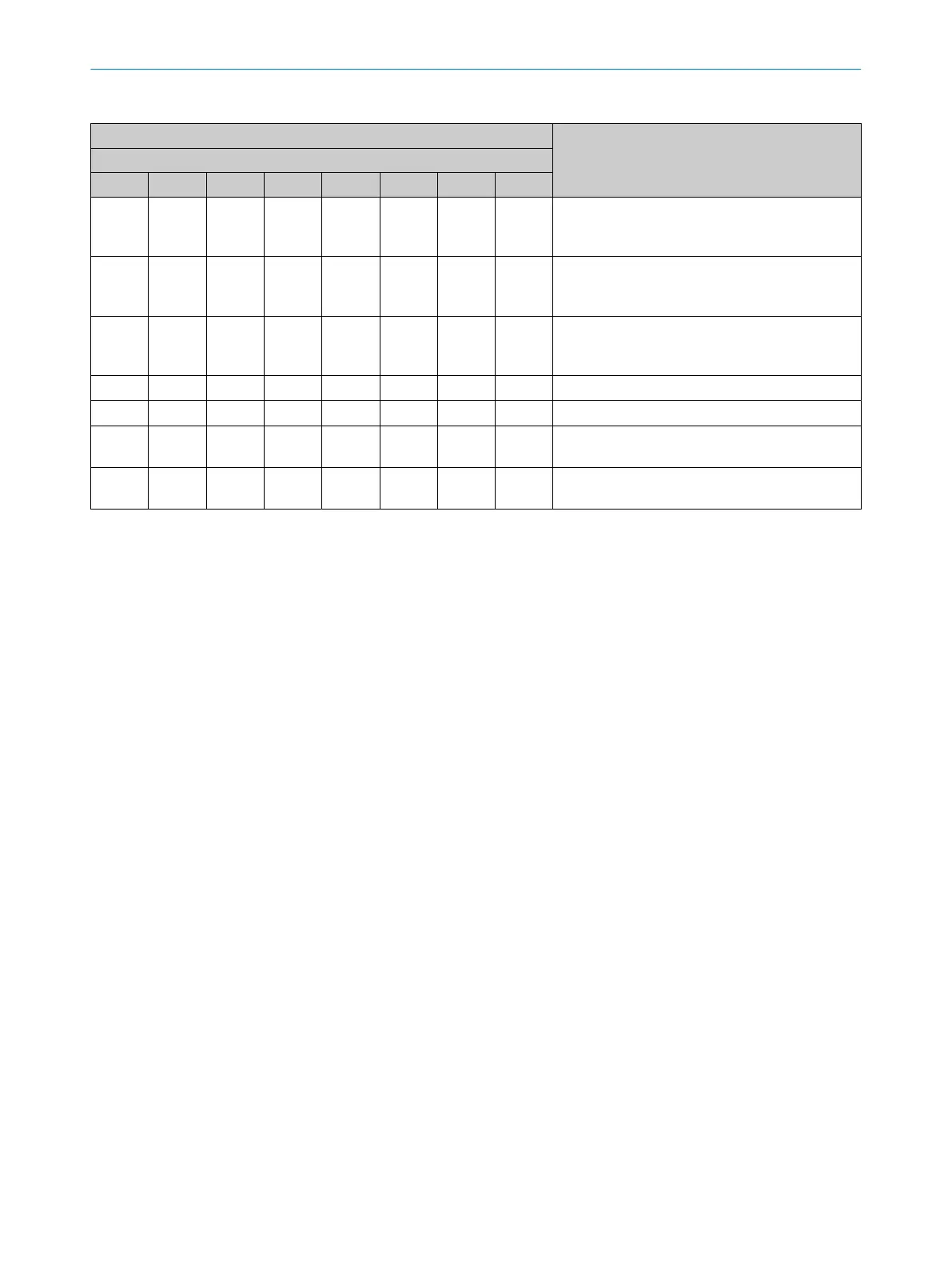
Table 19: Indication of the alignment quality
LEDs Meaning
Diagnostics LEDs
1 2 3 4 5 6 7 8
o o o o o o o o
Alignment is inadequate, or the protective field is
a
t least partially interrupted. The receiver cannot
synchronize with the sender.
O Blue o o o
At least one beam is synchronized.
Ho
wever, the alignment is inadequate, or the pro‐
tective field is at least partially interrupted.
O Blue O Blue o o
The alignment or the signal strength is still not
suf
ficient for stable availability, or the protective
field is at least partially interrupted.
1)
O Blue O Blue O Blue o
Alignment is good, stable availability.
1)
2)
O Blue O Blue O Blue O Blue
Alignment is very good.
1)
O Blue O Blue
The topmost light beam (far from system plug) is
s
ynchronized.
O Blue O Blue
The bottommost light beam (near system plug) is
synchronized.
o LED of
f. Ö LED flashes. O LED illuminates.
1)
If external device monitoring is configured and there is an EDM warning, diagnostic LED 1 flashes, while the other diagnostic LEDs 2, 3 and
4 indicate the alignment quality. If there is an error on the reset pushbutton, diagnostic LED 4 flashes, while the other diagnostic LEDs 1, 2
and 3 indicate the alignment quality.
2)
If the protective fields are very wide, there is a possibility that diagnostic LED 4 does not light up, even with optimal alignment.
Further topics
•
"Indic
ations when switching on", page 70
8.5 Check during commissioning and modifications
The test is intended to ensure that the hazardous area is monitored by the protective
de
vice and any attempted access to the hazardous area is prevented.
b
Carry out the checks specified in the test plan of the manufacturer of the machine
and the operating entity.
8 C
OMMISSIONING
64
O P E R A T I N G I N S T R U C T I O N S | deTec4 8027140/2021-11-04 | SICK
Subject to change without notice