Table 11: System connection pin assignment (male connector, M12, 5-pin)
PIN Wire color
1)
s S
ender r Receiver
1 Brown +24 V DC (voltage supply
input)
+24 V DC (voltage supply
input)
2 White In2
(
laser alignment aid push‐
button)
OSSD1 (switching output 1)
3 Blue 0 V DC (voltage supply
in
put)
0 V DC (voltage supply
input)
4 Black In1
(
laser alignment aid switch)
OSSD2 (switching output 2)
5
2)
Gray MFP1
N
ot assigned
MFP1
Not assigned
1)
Applies to the connecting cables recommended as accessories.
2)
If the sender and the receiver are not connected, pin 5 can remain unassigned for a single system and,
f
or example, a 4-pin cable with a 4-pin female connector can be used.
Further topics
•
"Int
egration in electrical control", page 30
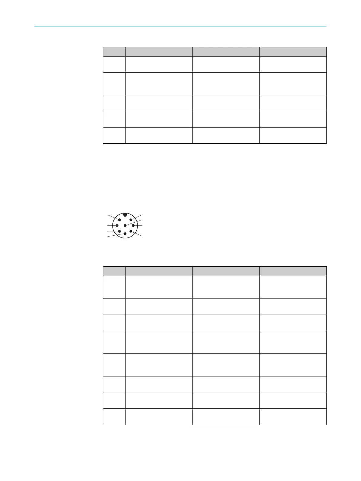
6.3 System connection (M12, 8-pin)
Figure 35: System connection (male connector M12, 8-pin)
T
able 12: System connection pin assignment for SP1 system plug (M12 male connector, 8-pin)
PIN Wire color
1)
s S
ender r Receiver
1 White Not assigned In3
RES (reset pushbutton
input)
2 Brown +24 V DC (voltage supply
in
put)
+24 V DC (voltage supply
input)
3 Green Not assigned MFP3
Not assigned
4 Yellow Not assigned In4
EDM (e
xternal device moni‐
toring input)
5 Gray In2
(
laser alignment aid push‐
button)
OSSD1 (switching output 1)
6 Pink In1
(
laser alignment aid switch)
OSSD2 (switching output 2)
7 Blue 0 V DC (voltage supply
in
put)
0 V DC (voltage supply
input)
8 Red MFP1
N
ot assigned
MFP1
Not assigned
1)
Applies to the connecting cables recommended as accessories.
ELECTRICAL INSTALLATION 6
8027140/2021-11-04 | SICK O P E R A T I N G I N S T R U C T I O N S | deTec4
51
Subject to change without notice