Installation
10
SICK Optic-Electronic
Bar Code Scanners
2
CONNECTORS AND PINOUTS
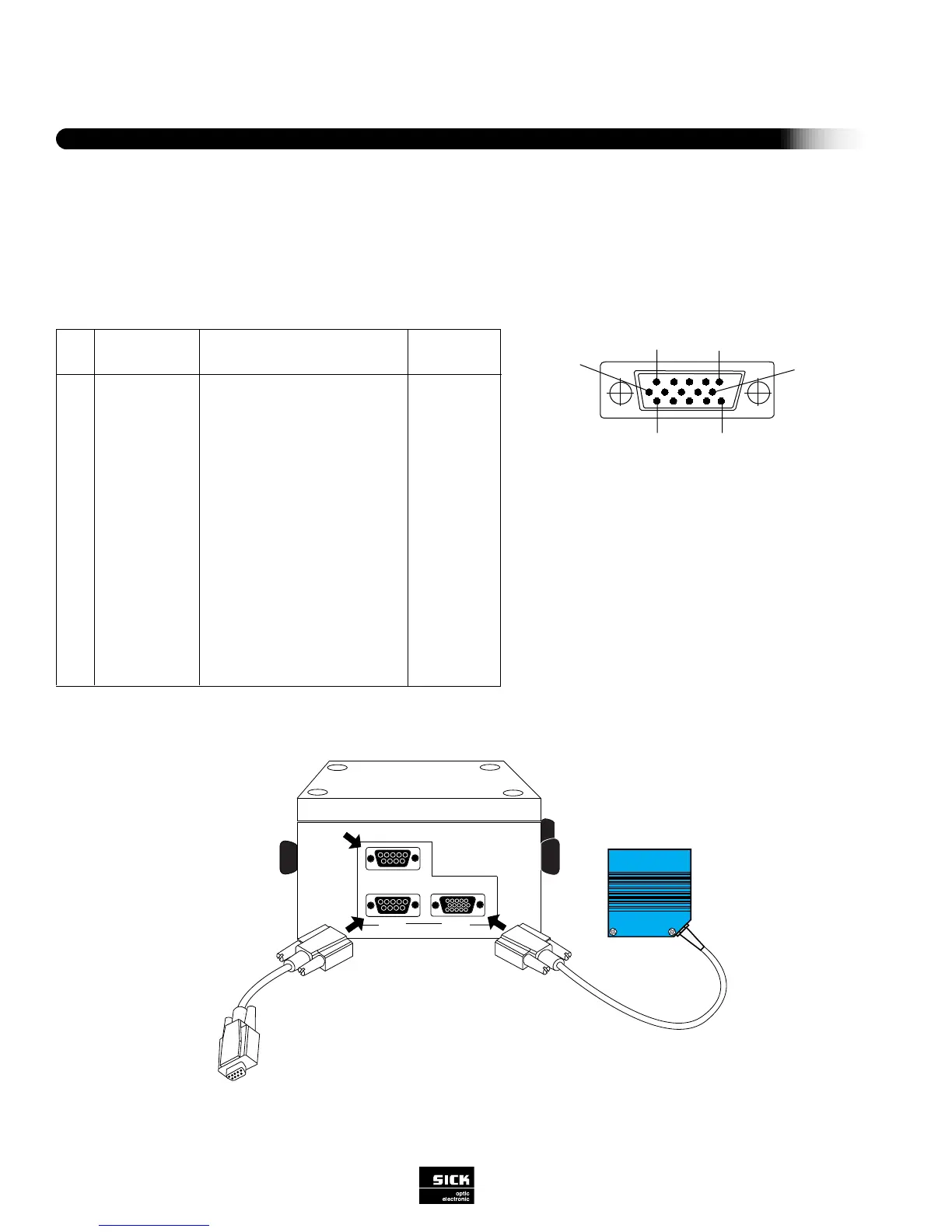
Make signal and power connections as explained below under “Power Supply Connections.” As a general precaution, shield all
lines carrying data and keep them as short as possible. Do not route them adjacent to other cables that could cause electromag-
netic interference. CLV interface connections consist of a single 15-pin connector. Refer to Figure 2-3.
1
5
1611
10
Figure 2-3 CLV Interface Ports
(1) 24 V DC input for Teach Mode
(2) 24 V DC Output
(3) External Sensor input (24 V DC @
100mA) for trigger
Figure 2-4 PS 52 Power Supply Connectivity
1
2
3
4
5
6
7
8
9
10
11
12
13
14
15
-
DC +4.5...+30 V
Sensor 2
Result 3
Term RS 422
GND
RD+ (RS 422/485)
RD- (RS 422/485)
TD+ (RS 422/485)
TD- (RS 422/485)
RxD (RS 232)
TxD (RS 232)
Result 1
Result 2
Sensor 1
Sensor GND
-
Supply voltage
Switching input teach-in (match code 1)
Switching output (to PLC)
Termination for data interface 1
Ground
Data interface 1 (receiver)
Data interface 1 (receiver)
Data interface 1 (transmitter)
Data interface 1 (transmitter)
Data interface 2 (receiver)
Data interface 2 (transmitter)
Switching output (to PLC)
Switching output (to PLC)
Switching input for ext. reading pulse
Common ground (all inputs)
Shield
red
orange
green
yellow
black
pink
violet
white
gray
blue
brown
black/white
turquoise
red/white
brown/white
-
FunctionSignalPin
Wire colors
of cable
no. 6010137
6