Chapter 5 Operating Instructions
CLV 42x bar code scanner
5-2 © SICK AG · Division Auto Ident · Germany · All rights reserved 8 009 981/O078/16-08-2004
Electrical connection
Connect and configure the CDB 420 or CDM 420 Connection Module as described in the
“
CDB 420 Connection Module“ Operating Instructions (order no. 8 010 001,
German/English version)
respectively in the “CDM 420 Connection Module“ Operating
Instructions (order no.
8 010 004, German/English version).
Note Diagramms showing you how to connect the CDB 420 and CDM 420 Connection Modules
are also available in the “CLV Connect“ PC program. This software is available on the
“Manuals & Software“ CD, which is included in the scope of delivery of the ICR.
The software can also be downloaded from the SICK home page (www.sick.de) at “Service&
Support/ Downloadpool“. It can be called up using a standard HTML browser (e. g. Internet
Explorer
TM
).
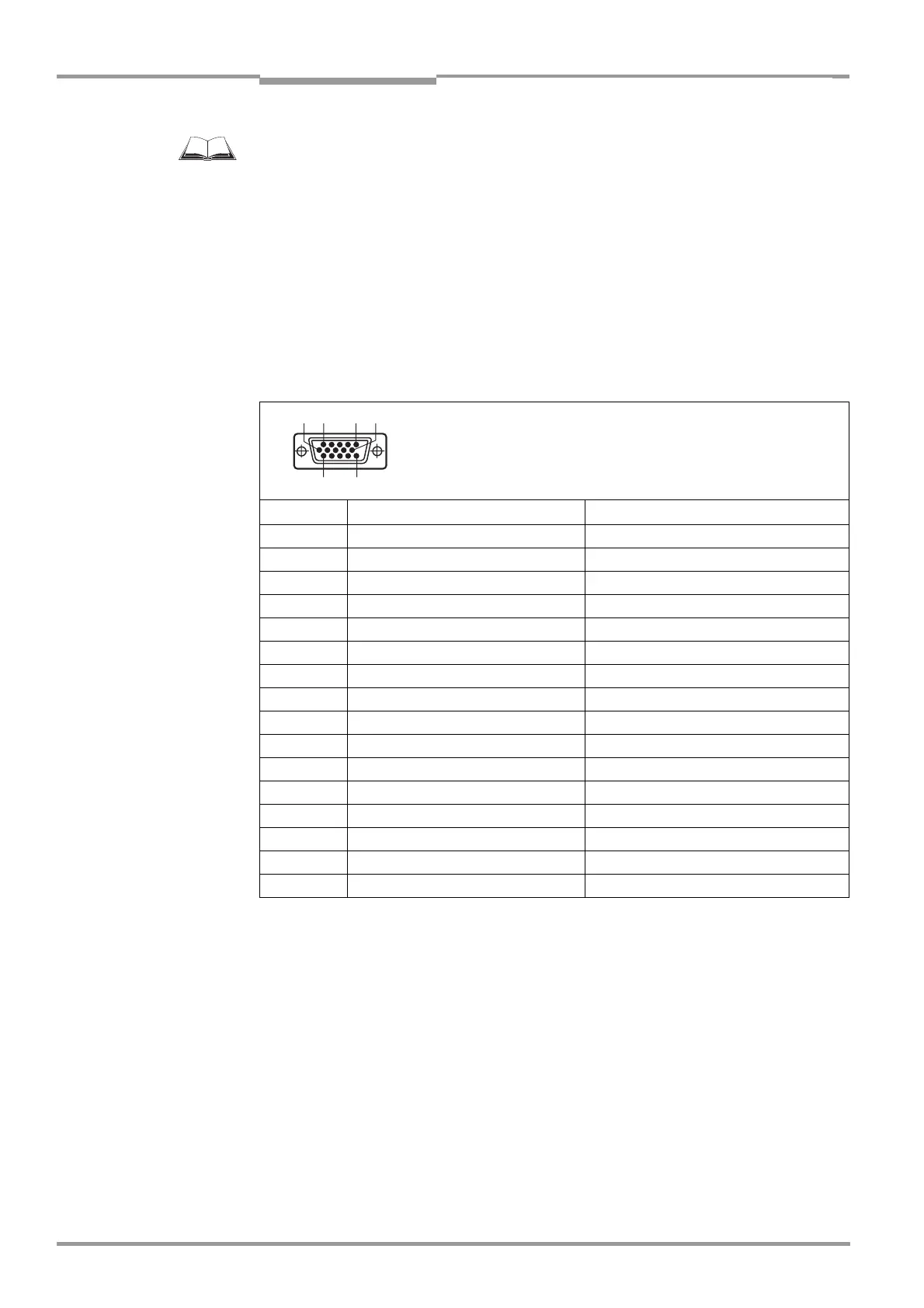
5.3 Connector pin assignment
Pin Signal Function
1 10 to 30 V DC Power supply
2 RxD (Terminal) Terminal interface (receiver)
3 TxD (Terminal) Terminal interface (transmitter)
4 Sensor 2 Switching input, variable function
5 GND Ground
6 RD+ (RS 422/485) Host interface (receiver)
7 RD– (RS 422/485); RxD (RS 232) Host interface (receiver)
8 TD+ (RS 422/485) Host interface (transmitter)
9 TD– (RS 422/485); TxD (RS 232) Host interface (transmitter)
10 CAN H CAN-Bus (IN/OUT)
11 CAN L CAN-Bus (IN/OUT)
12 Result 1 Switching output, variable function
13 Result 2 Switching output, variable function
14 Sensor 1 Switching input for external reading pulse
15 SensGND Common ground for all inputs
– – Shield
Table 5-1: Pin assignment of the 15-pin D Sub HD plug
56
11
10
15
1