Chapter 5 Operating Instructions
CLV 42x bar code scanner
5-8 © SICK AG · Division Auto Ident · Germany · All rights reserved 8 009 981/O078/16-08-2004
Electrical connection
5.5.7 Connecting the "Sensor 1" switching input
If a reading procedure is to be triggered on the CLV by an external sensor, the reading pulse
sensor must be connected to the "Sensor 1" switching input. The trigger type is selected in
the default setting of the CLV.
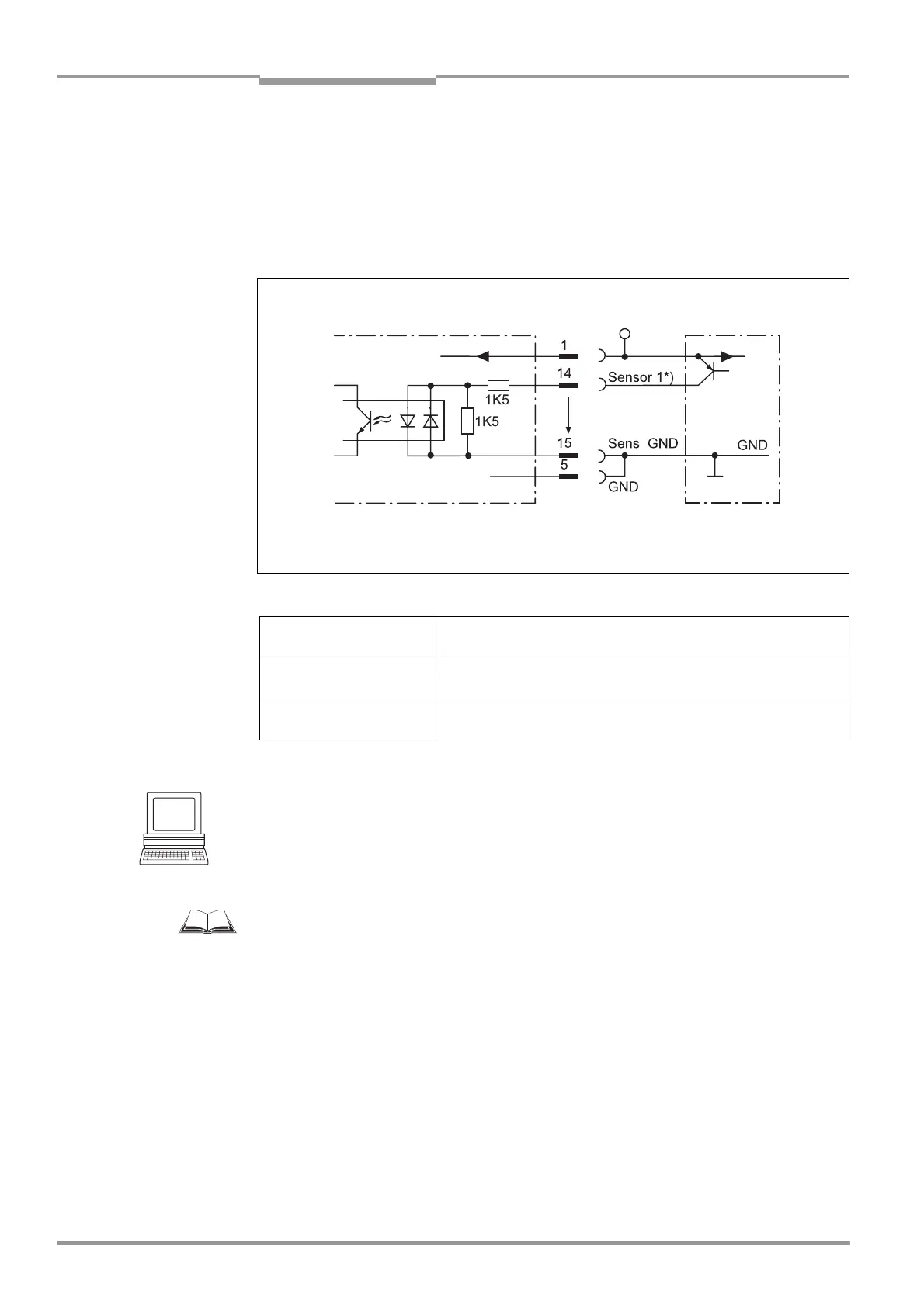
Fig. 5-4 shows the connections for the "Sensor 1" switching
input. Table 5-6 contains the characteristic data for this input.
Connect the reading pulse sensor as is shown in Fig. 5-4.
Tip
You can change the switching mode (polarity, debouncing, response for first pulse after
power-up) of the "Sensor 1" switching input on the
DEVICE CONFIGURATION tab in the CLV
Setup program.
Click the READING TRIGGER PARAMETERS button. Edit dialog window.
Download all changes to CLV.
For connecting the switching input via the CDB 420 or CDM 420 Connection Module, see
the “CDB 420 Connection Module“ Operating Instructions (order no.
8 010 001,
German/English version) respectively the “CDM 420 Connection Module“ Operating
Instructions (order no.
8 010 004, German/English version).
Note An external pulse is not required for "Percentage Evaluation" mode.
5.5.8 Connecting the "Sensor 2" switching input
The input has the following functions:
• Trigger source for teaching in the match code 1
• Conveyor increment input
• External trigger source for end of the reading interval
• Trigger source for switching over the dynamical reading configuration
Fig. 5-4: Connections of the "Sensor 1" switching input
Switching mode Current at the input starts the reading interval on the CLV.
(default setting: active high, debouncing: max. 30 ms (standard))
Properties – optodecoupled, non-interchangeable
– can be connected to PNP output on a sensor
Electrical values Low: –1V ≤ V
i
≤ +1 V High: +3 V ≤ |V
i
| ≤ +28 V
–0.3 mA ≤ I
i
≤ +0.3 mA +1.4 mA ≤ |I
i
| ≤ +18 mA
Table 5-6: Characteristic data of the "Sensor 1" switching input
CLV 42x V
S
PNP sensor
V
S
= +10 to +30 V DC *) V
imax
= 28 V!
V
S
V
S
V
i