Chapter 5 Operating Instructions
CLV 42x bar code scanner
5-6 © SICK AG · Division Auto Ident · Germany · All rights reserved 8 009 981/O078/16-08-2004
Electrical connection
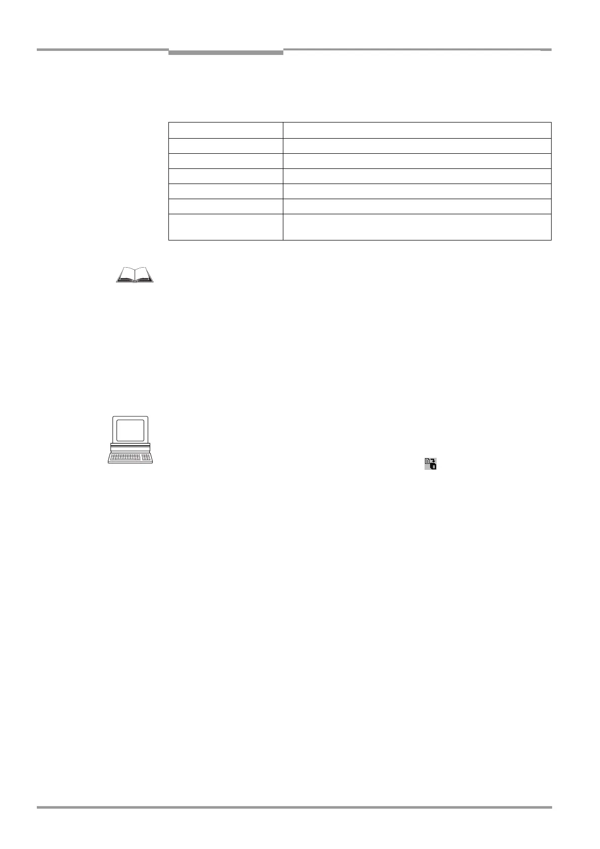
In the default setting, the CLV communicates with the host via the host interface using the
values shown in
Table 5-5.
For connecting the host interface via the CDB 420 or CDM 420 Connection Module, see the
“CDB 420 Connection Module“ Operating Instructions (order no. 8 010 001, German/
English version)
respectively the “CDM 420 Connection Module“ Operating Instructions
(order no.
8 010 004, German/English version).
Terminating the RS 422 interface
The interface can be terminated in the CDB 420 or CDM 420 connection module.
See Operating Instructions for the "CDB 420 or CDM 420 connection module".
Activating the RS 232 interface
The RS 232 interface can be activated with the CLV Setup program:
1. Choose the HOST INTERFACE tab.
2. Choose the "RS 232" option from the HARDWARE drop-down list under DATA FORMAT.
3. Perform a download to the CLV. This is done by clicking in the toolbar.
The DOWNLOAD PARAMETER dialog window is displayed.
4. Confirm the dialog window by selecting the PERMANENT save option.
The CLV uses the RS 232 version of the host interface.
TIP The communication parameters can be changed, if necessary, on the HOST INTERFACE tab.
To do so, change the values under DATA FORMAT and INTERFACE PROTOCOL.
5.5.5 Connecting the CAN interface
For information on the connection and parameterization of the CLV for use in a SICK scanner
network or in a CANopen network, see the Operating Instructions
"Application of the CAN
interface" (no. 8 009 180, English version).
Parameter Value
Interface model RS 422/485
Data transfer rate 9,600 bd
Data bits 8
Parity none
Stop bits 1
Protocol SICK (start character: STX, stop character: ETX, no request for
repeat: none, timeout: 50 ms)
Table 5-5: Communication parameters for the host interface (default setting)