grounding point 1 grounding point 2
Electro-
optical
signal
isolator
Electro-
optical
signal
isolator
e. g. PLC
Power
supply
unit
SICK
device
shielded electrical cablemetal housing
fiber optic cable
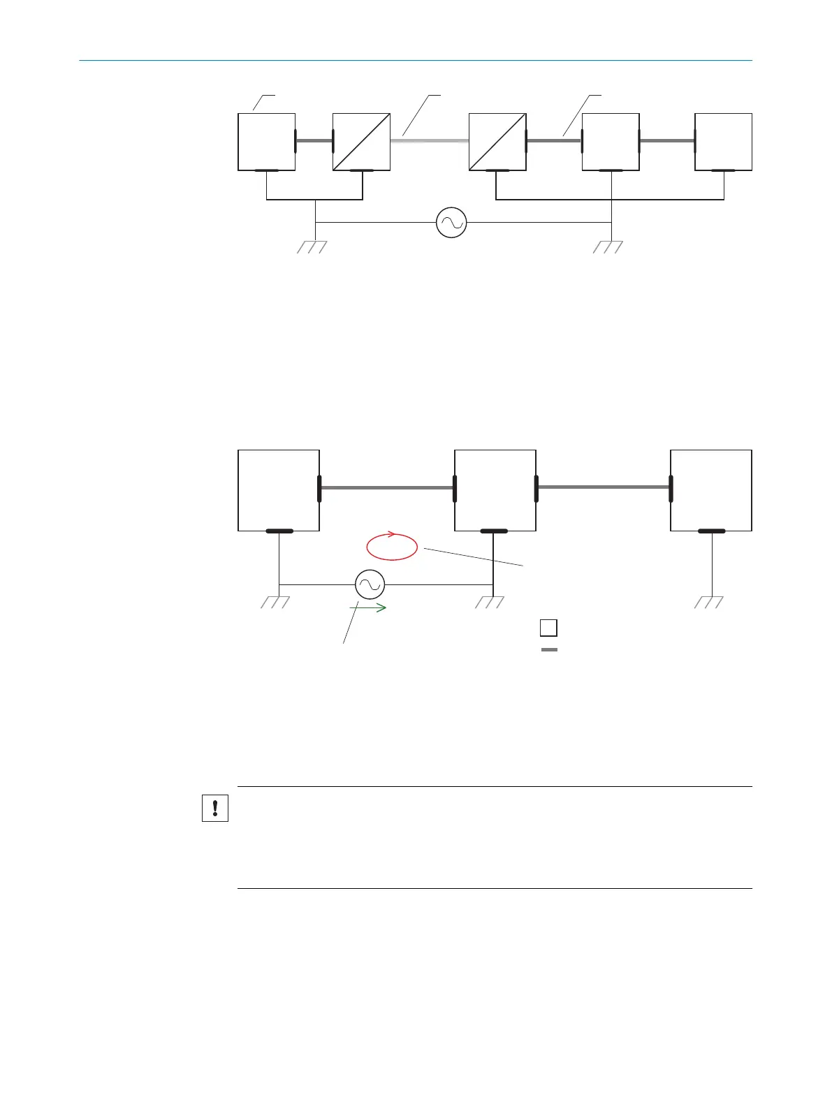
Figure 23: Prevention of equipotential bonding currents in the system configuration by the use of
electro-optical signal isolators
The use of electro-optical signal isolators between the islands isolates the ground loop.
Within the islands, a stable equipotential bonding prevents equalizing currents on the
cable shields.
Measures for small system installations
For smaller installations with only slight potential differences, insulated mounting of the
device and of peripheral devices may be a sufficient solution.
SICK
device
closed current loop with equalizing
currents via cable shield
grounding point 2
grounding point 1
grounding potential difference
e. g. PLC
e. g. sensor
I
U
= metal housing
= shielded electrical cable
Figure 24: Prevention of equipotential bonding currents in the system configuration by the insu‐
lated mounting of the device
Even in the event of large differences in the ground potential, ground loops are effec‐
tively prevented. As a result, equalizing currents can no longer flow via the cable shields
and metal housing.
NOTICE
The voltage supply for the device and the connected peripheral devices must also guar‐
antee the required level of insulation.
Under certain circumstances, a tangible potential can develop between the insulated
metal housings and the local ground potential.
ELECTRICAL INSTALLATION 6
8019588/2017-01-20 | SICK O P E R A T I N G I N S T R U C T I O N S | CLV63x, CLV64x, CLV65x
35
Subject to change without notice