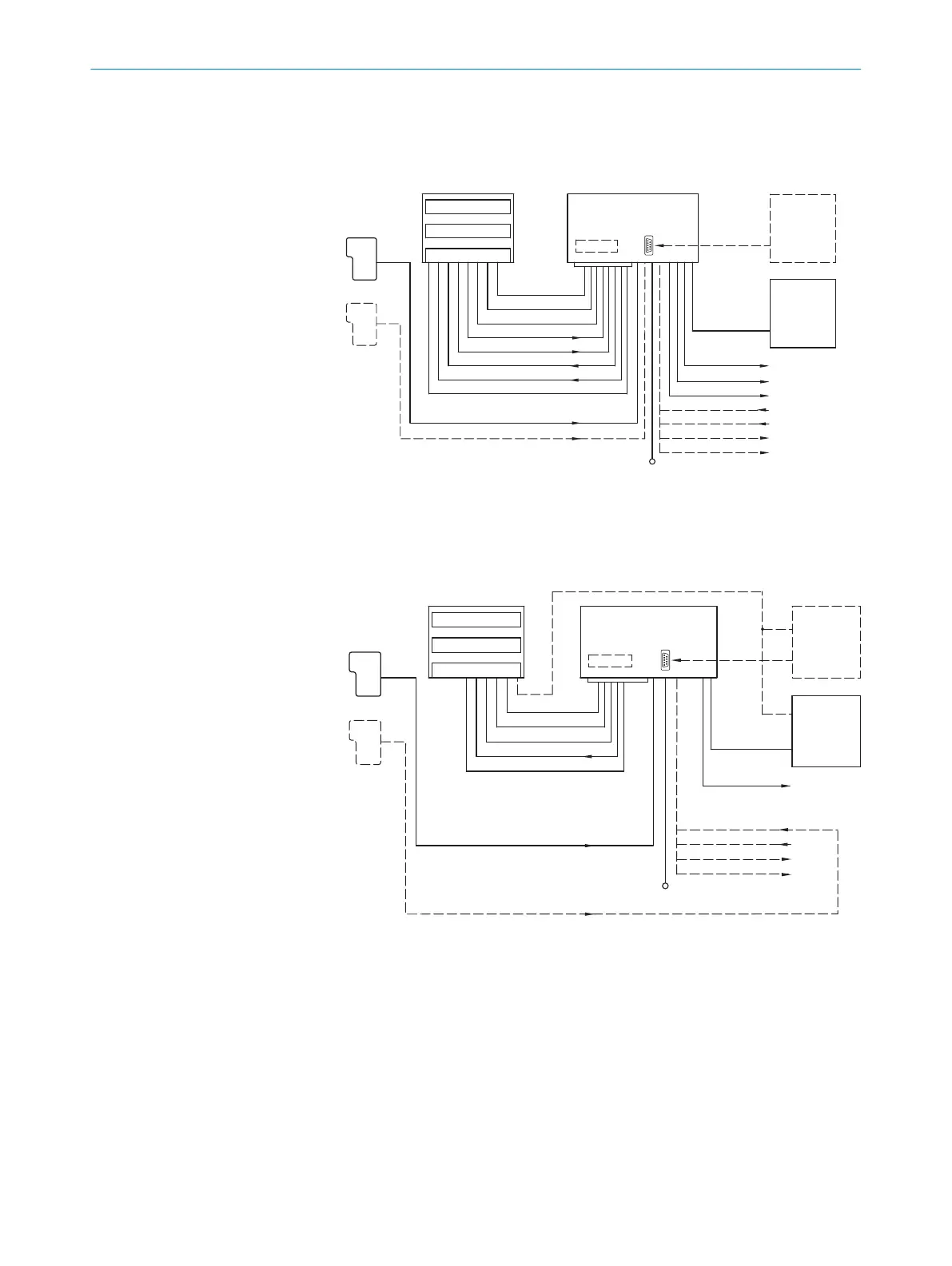
6.5 Connection diagrams
Standard version, 15-pin male connector
CDB620/CDM420
Connection module
"Aux" (serial)
"Host" (serial)
"Host" (serial)
Decoder
Scanner
Interface
"Aux" (serial)
PLC
PLC
PLC
PLC
PLC
PLC
CAN bus
PC
HOST
"CAN"
"Result 1"
"(Aux) In 1"
*)
"(Aux) In 2"
*)
"(Aux) Out 1"
*)
"(Aux) Out 2"
*)
"Result 2"
DC 18 ... 30 V
"CAN"
"Result 1"
"Result 2"
"Sensor 1"
"Sensor 2"
"Sensor 1"
"Sensor 2"
DC 18 ... 30 V
*) CMC600 required
Photo-electric
switch
Reading pulse
Path Increment
Reading pulse
CMC600
Bar code scanner
D-Sub-HD, 15-pin
Figure 29: Standard version: Electrical connections on the bar code scanner with connecting
cable
Ethernet version, 12-pin male connector
Decoder
Scanner
Interface
PC
*) CMC600 required
DC 18 ... 30 V
CDB620/CDM420
Connection module
CMC600
"Aux"
(serial)
"Host" (serial)
"CAN"
CAN bus
PLC
PLC
PLC
"Host" (serial)
"Aux" (serial)
"CAN"
"Sensor 1"
"Sensor 1"
"Sensor 2"
DC 18 ... 30 V
"Ethernet" (Host/Aux)
"(Aux) In 1"
*)
"(Aux) In 2"
*)
"(Aux) Out 1"
*)
"(Aux) Out 2"
*)
Photo-electric
switch
Reading pulse
Path Increment
Reading pulse
Bar code scanner
M12, 12-pin/4-pin
HOST
Figure 30: Ethernet version: Electrical connections on the bar code scanner with connector (12-
pin)
ELECTRICAL INSTALLATION
6
8019588/2017-01-20 | SICK O P E R A T I N G I N S T R U C T I O N S | CLV63x, CLV64x, CLV65x
39
Subject to change without notice