6.3 Wiring notes
NOTICE
Faults due to incorrect wiring.
Incorrect wiring may result in operational faults.
■
For data transmission, use only screened cables with twisted-pair wires.
■
Follow the wiring notes precisely.
NOTE
Preassembled cables can be found online at:
b
www.sick.com/CLV63x
b
www.sick.com/CLV64x
b
www.sick.com/CLV65x
All electrical connections of the device are configured as M12 round connectors or as a
cable with D-Sub-HD male connector. The IP65/IP69K enclosure rating is only achieved
with screwed plug connectors or cover caps.
6.4 Pin allocation of the connections
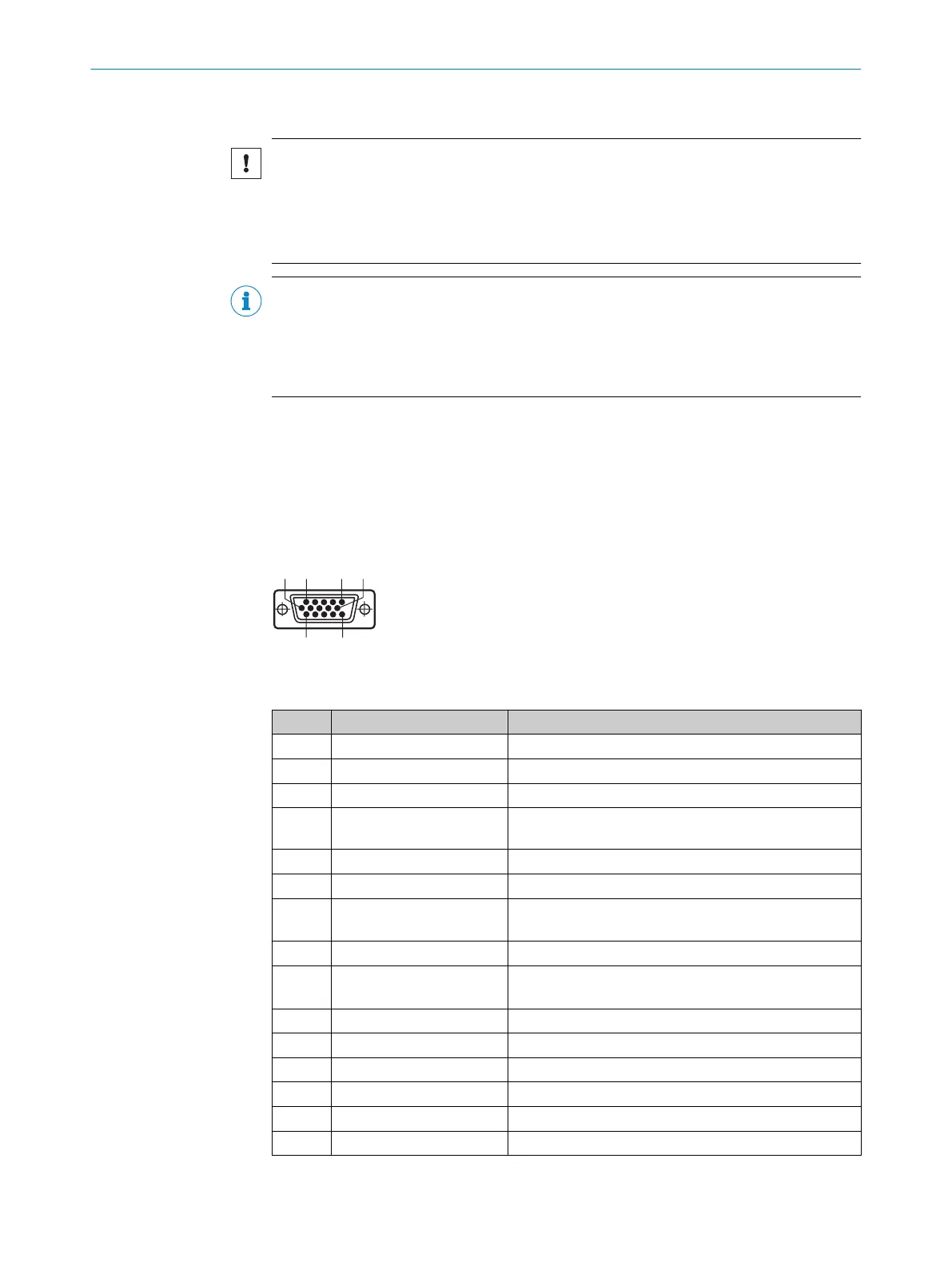
Device connections with cable and male connector (standard version)
Figure 25: Male connector, D-Sub-HD, 15-pin
Pin Signal Function
1 DC 18 ... 30 V Supply voltage
2 RxD (AUX) AUX interface (receiver)
3 TxD (AUX) AUX interface (sender)
4 Sensor 2 Digital switching input (function adjustable, e.g. external
reading cycle)
5 GND Ground
6 RD+ (RS-422/485) Host interface (receiver)
7 RD– (RS-422/485);
RxD (RS-232)
Host interface (receiver)
8 TD+ (RS-422/485) Host interface (sender)
9 TD– (RS-422/485);
TxD (RS-232)
Host interface (sender)
10 CAN H CAN bus (IN/OUT)
11 CAN L CAN bus (IN/OUT)
12 Result 1 Digital switching output, function can be set
13 Result 2 Digital switching output, function can be set
14 Sensor 1 Digital switching input for external reading cycle
15 SensGND Common ground for switching inputs
Table 5: Standard version: Pin assignment on 15-pin D-Sub-HD male cable connector
6 ELECTRICAL INSTALLATION
36
O P E R A T I N G I N S T R U C T I O N S | CLV63x, CLV64x, CLV65x 8019588/2017-01-20 | SICK
Subject to change without notice