Pin Signal Function
- – Screen
Table 5: Standard version: Pin assignment on 15-pin D-Sub-HD male cable connector
Device connections with connector (Ethernet version)
Figure 26: Female connector, M12, 4-pin, A-coding
Pin Signal Function
1 TD+ Sender+
2 RD+ Receiver+
3 TD- Sender-
4 RD- Receiver-
- - Screen
Table 6: Ethernet version: Pin assignment on the 4-pin M12 female connector
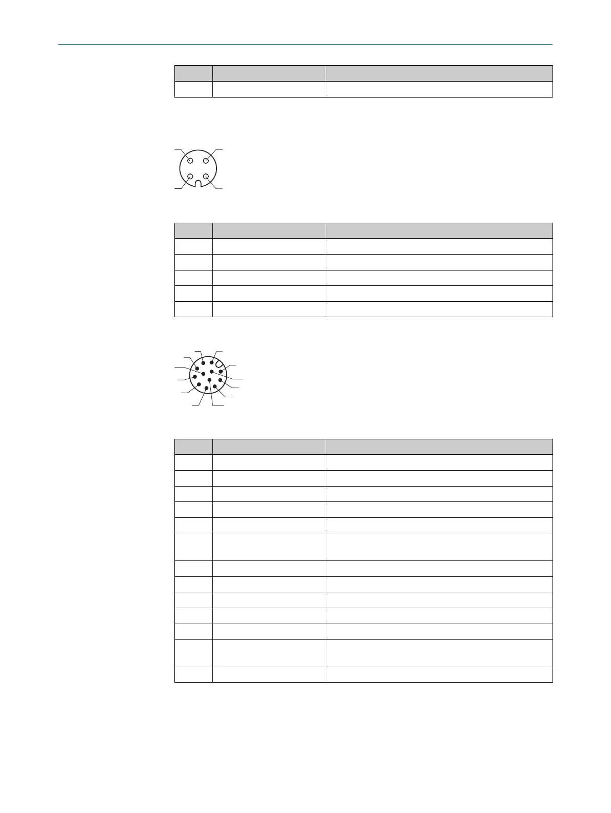
Figure 27: Male connector, M12, 12-pin, A-coding
Pin Signal Function
1 GND Ground
2 DC 18 ... 30 V Supply voltage
3 CAN L CAN bus (IN/OUT)
4 CAN H CAN bus (IN/OUT)
5 TD+ (RS-422/485) Host interface (sender)
6 TD– (RS-422/485);
TxD (RS-232)
Host interface (sender)
7 TxD (AUX) AUX interface (sender)
8 RxD (AUX) AUX interface (receiver)
9 SensGND Sensor 1 switching input ground
10 Sensor 1 Digital switching input (external reading cycle)
11 RD+ (RS-422/485) Host interface (receiver)
12 RD– (RS-422/485);
RxD (RS-232)
Host interface (receiver)
- – Screen
Table 7: Ethernet version: Pin assignment on 12-pin M12 male connector
The “Sensor 2“, “Result 1” and “Result 2” connections are only available on the device
with cable and male connector (standard version) as well as for the Ethernet version via
the CDB620 connection module with the CMC600 parameter memory module.
ELECTRICAL INSTALLATION 6
8019588/2017-01-20 | SICK O P E R A T I N G I N S T R U C T I O N S | CLV63x, CLV64x, CLV65x
37
Subject to change without notice