3
1
7
2
6
5
4
8
13
14
17
15
9
10
12
16
11
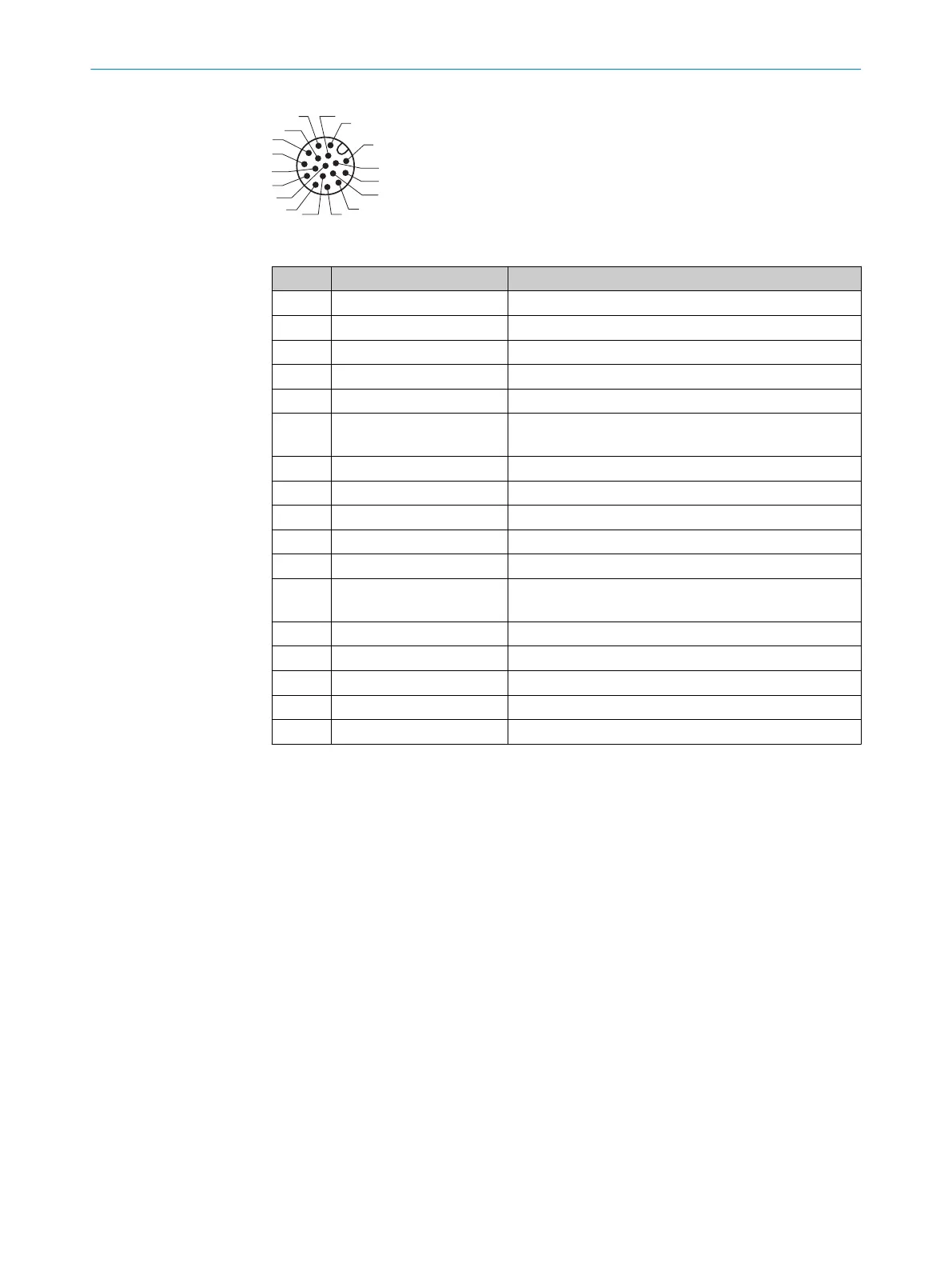
Figure 28: Male connector, M12, 17-pin, A-coding
Pin Signal Function
1 GND Ground
2 DC 18 ... 30 V Supply voltage
3 CAN L CAN bus (IN/OUT)
4 CAN H CAN bus (IN/OUT)
5 TD+ (RS-422/485) Host interface (sender)
6 TD– (RS-422/485);
TxD (RS-232)
Host interface (sender)
7 TxD (AUX) AUX interface (sender)
8 RxD (AUX) AUX interface (receiver)
9 SensGND Sensor 1 switching input ground
10 Sensor 1 Digital switching input (external reading cycle)
11 RD+ (RS-422/485) Host interface (receiver)
12 RD– (RS-422/485);
RxD (RS-232)
Host interface (receiver)
13 Result 1 Digital switching output, function can be set
14 Result 2 Digital switching output, function can be set
15 Sensor 2 Digital switching input (external reading cycle)
16 – –
17 – –
Table 8: Ethernet version: pin assignment on 17-pin M12 male connector
6 ELECTRICAL INSTALLATION
38
O P E R A T I N G I N S T R U C T I O N S | CLV63x, CLV64x, CLV65x 8019588/2017-01-20 | SICK
Subject to change without notice