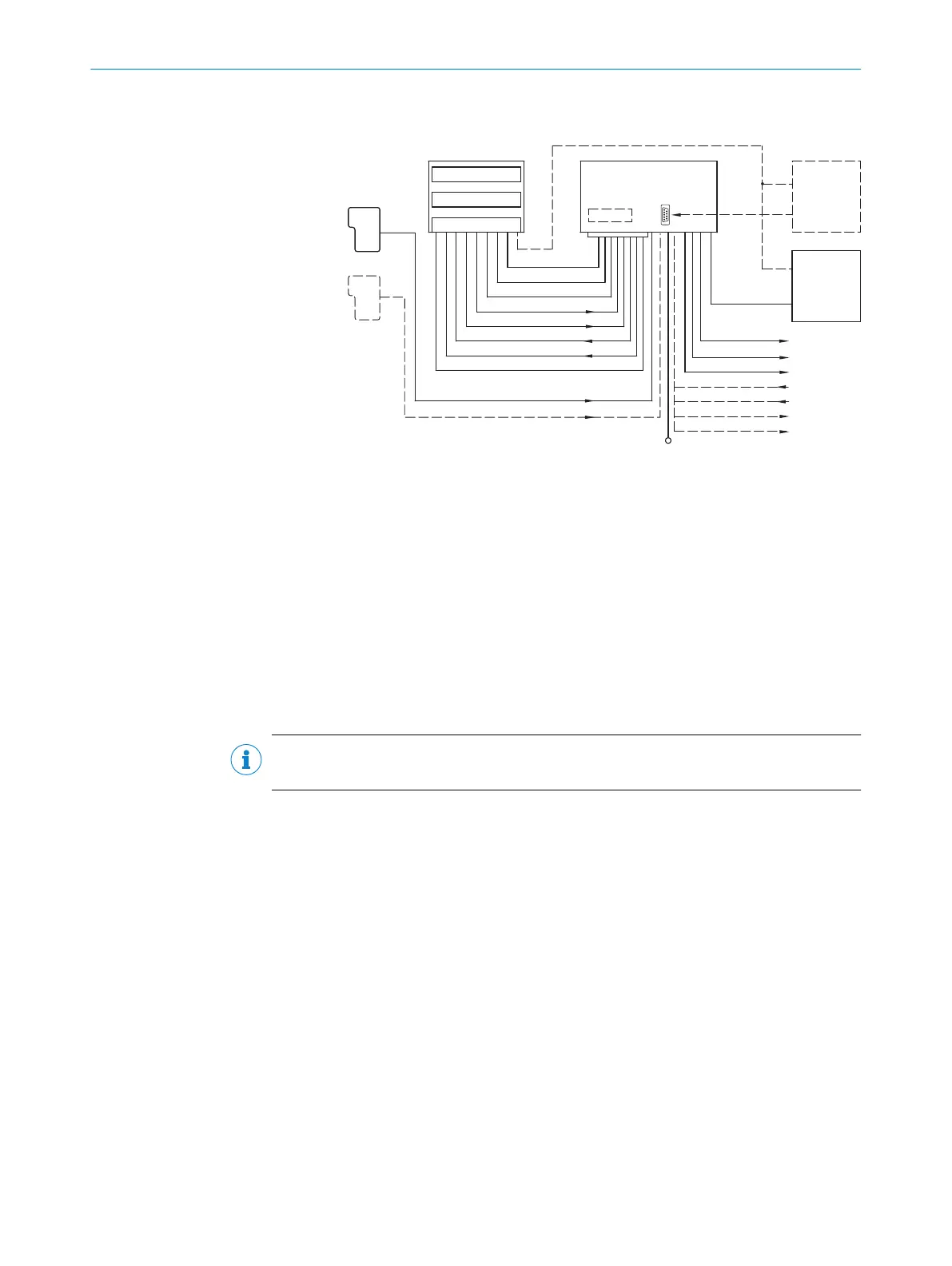
Ethernet version, 17-pin male connector
"Sensor 1"
"Sensor 2"
Bar code scanner
M12, 17-pin/4-pin
Decoder
Scanner
Interface
PC
*) CMC600 required DC 18 ... 30 V
CDB650
Connection module
CMC600
"Aux"
(serial)
"Host" (serial)
"Ethernet" (Host/Aux)
"Host" (serial)
"Aux" (serial)
"CAN"
"Result 1"
"Result 2"
"Sensor 1"
"Sensor 2"
DC 18 ... 30 V
PLC
PLC
PLC
PLC
PLC
PLC
CAN bus
"CAN"
"Result 1"
"EXT. IN 1"
*)
"EXT. IN 2"
*)
"EXT. OUT 1"
*)
"EXT. OUT 2"
*)
"Result 2"
Photo-electric
switch
Reading pulse
Path Increment
Reading pulse
HOST
Figure 31: Ethernet version: Electrical connections on the bar code scanner with connector (17-
pin)
6.5.2 Connecting connection modules to devices with heating
General notes
■
Electrical connections may only be made when there is no power in the system.
■
Do not do any connection work at temperatures under 0 °C!
■
The wire cross section of the incoming supply cables to the connection module
must be 0.75 mm
2
.
■
The required supply voltage at the connection module is DC 24 V ±10%.
■
Due to voltage drops, long cables require a larger wire cross section in line with
valid standards.
NOTE
The device loses its UL certification if the connecting cables are extended over 2 m.
Using connection module CDM420-0001
The incoming/continuing supply cables in the CDM420-0001 are connected on termi‐
nal block U
IN
of the additional connection circuit board.
6 ELECTRICAL INSTALLATION
40
O P E R A T I N G I N S T R U C T I O N S | CLV63x, CLV64x, CLV65x 8019588/2017-01-20 | SICK
Subject to change without notice