timers, such as photoelectric sensors or incremental encoders, enable reading pulses
independent of the control. The reading results are provided for further processing by
the data interfaces.
In principle, the codes can be recorded on any side on still or moving objects in a con‐
veyor system (single-side reading).
By combining several devices, it is possible to record several sides in one passage
(multi-side reading).
To record the codes, the device generates a scan line (line scanner).
Line scanner with oscillating mirror
The oscillating mirror also moves the scan line vertically to the scan direction from the
resting position to both sides with a low oscillation frequency. This means that the
device can also scan larger areas for bar codes.
The length of the scan line which can be used for evaluation (reading field height)
depends on the reading distance as a result of the V-shaped light emission.
The light pattern reflected by the bar code is recorded, processed and decoded. To con‐
trol this process, external sensors provide information about the reading pulse and the
conveyor speed (increment). The read results are released to the device's data interfa‐
ces and forwarded to a host/PC.
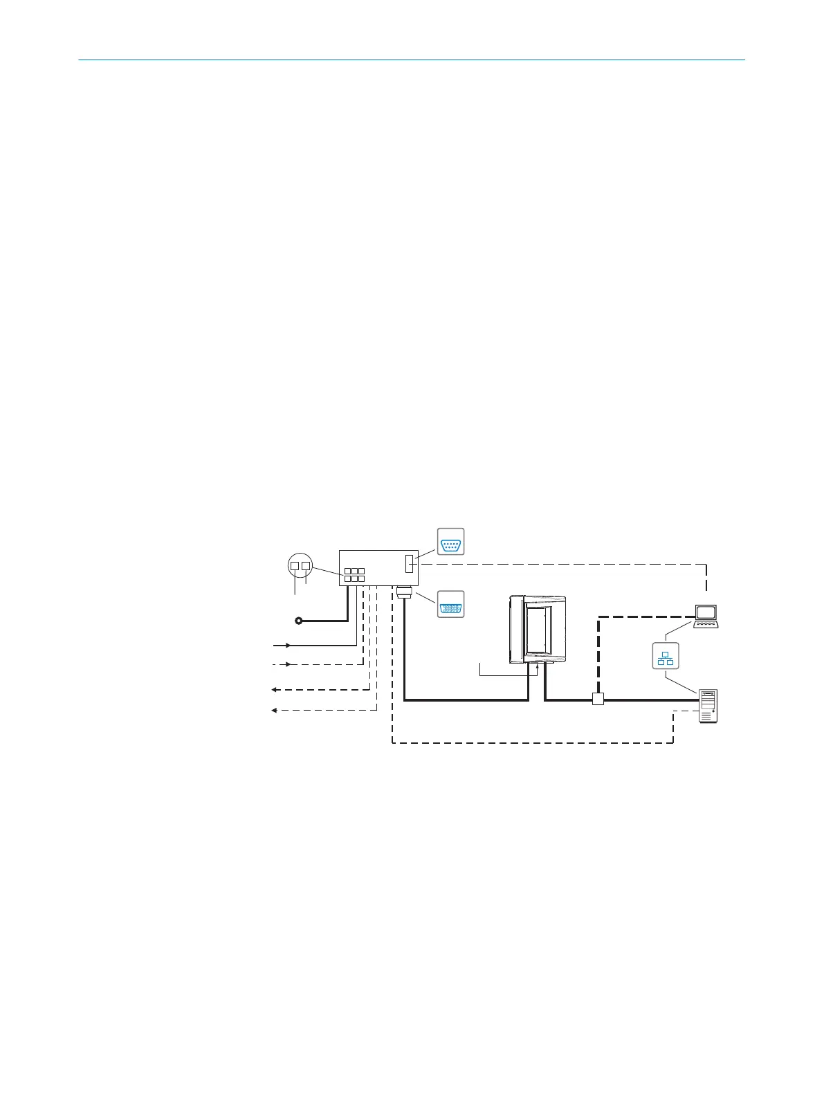
Detailed wiring of the device and the connections to the host/PC and the external sen‐
sors are described in chapter Electrical installation.
Block diagrams
“Ethernet” (HOST 2)
Input 2
(e.g. encoder)
Input 1
(e.g. external read cycle)
Output 1
(e.g. LED)
Output 2
(e.g. LED)
CLV69x-xxx0
“Serial RS-232/RS-422/485” (HOST 1), alternative to Ethernet host port
CDM420-0006
SerialSerial
e.g. cable
no. 6034414 (2m)
e.g. cable
no. 2055419 (2m)
Configuration
Diagnostics
SOPASSOPAS
SerialSerial
“HOST/AUX/I/O”
(AUX 1, HOST 1)
...
...
1
2
DC 18V ... 30V
GND
HOST
PC
e.g. cable no. 2014054 (2m)
“Serial RS-232” (AUX 1), alternative to Ethernet AUX port
“Ethernet” (AUX 2)
DC 18V ... 30V
Switching inputs/outputs = digital
“Ethernet”
Reading result
Cloning plug
no. 2062452
EthernetEthernet
Further data
processing
Figure 5: Facilities for connecting CLV69x, example
3.2.3.1 Object trigger control
The device needs a suitable external signal (trigger source) as notification of an object
being in the reading field to start an object-related read process. As standard, the start
signal is issued via an external read cycle sensor (e.g. photoelectric sensor). As soon as
an object has passed the reading cycle sensor, a time window (“reading interval”) is
opened in the device for the reading process.
Alternatively, a command triggers the read process via a data interface or the
SICK SENSOR network. In auto pulse mode, the device internally generates the reading
gate itself with an adjustable clock ratio.
The read cycle can be terminated in various ways. In the event of external triggering,
this is carried out via the read cycle source or a command, or internally via a timer or an
evaluation condition that needs to be met.
PRODUCT DESCRIPTION 3
8014396/ZMG8/2017-07-04 | SICK O P E R A T I N G I N S T R U C T I O N S | CLV69x
15
Subject to change without notice