5.3 Preparation for mounting
5.3.1 Mounting requirements
NOTICE
Radio interference may occur when the device is used in residential areas!
Only use the device in industrial environments (EN 61000-6-4).
■
Typical space requirement for device: See type-specific dimensional drawing and
reading field diagram.
■
Comply with technical data, such as the permitted ambient conditions for opera‐
tion of the device (e.g., temperature range, EMC interference emissions, ground
potential), see "Technical data", page 96.
■
To prevent condensation, avoid exposing the device to rapid changes in tempera‐
ture.
■
Protect the device from direct sunlight.
■
Device must only be mounted using the pairs of threaded mounting holes provided
for this purpose.
■
Shock and vibration-free mounting.
Equipment required
■
Mounting device (bracket) with sufficient load-bearing capacity and suitable
dimensions for the device.
■
2 x M6 screws
NOTE
The screws are used for mounting the device on a mounting device supplied by the
user. Screw length is dependent on the mounting base (wall thickness of the
bracket). When using an optional SICK bracket, the screws for mounting the device
are included with delivery.
■
Tool and tape measure
5.3.2 Mounting device
The device is mounted on the bracket using two M6 blind hole threads that are in pairs
on the narrow side of the device, see "Dimensional drawings", page 127.
The device can be installed using optional SICK brackets or customer-specific brackets.
SICK offers prefabricated brackets which are optimally suited for the mounting of the
device in a wide range of applications. See:
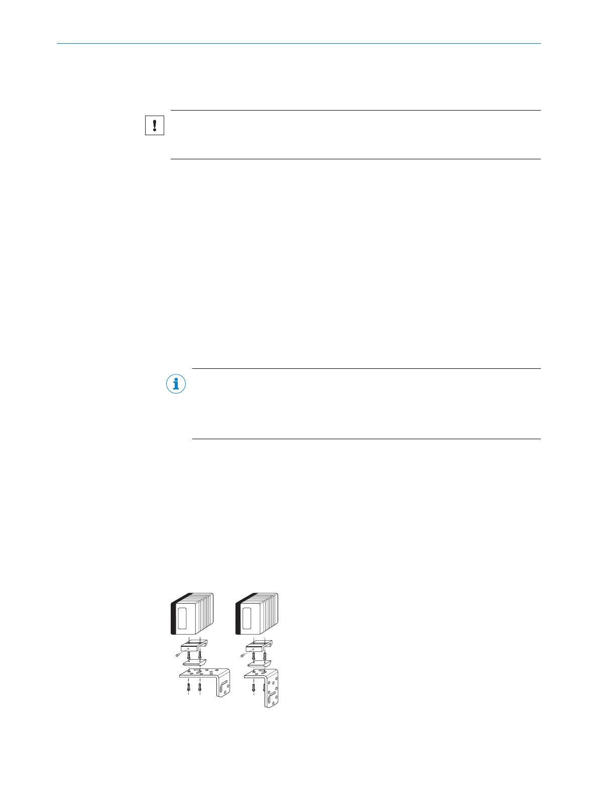
Example: The design of the bracket with adapter plate supports many different installa‐
tion variants, for example, as well as the alignment of the device in two axes.
Figure 11: Example of mounting a CLV69x with a quick clamping device and a mounting bracket
5 MOUNTING
22
O P E R A T I N G I N S T R U C T I O N S | CLV69x 8014396/ZMG8/2017-07-04 | SICK
Subject to change without notice