1. Connecting the switching outputs according to the application
2. For the thorough check of the switching functions, use a high resistance digital
voltmeter and wire the switching outputs with a load.
This avoids the display of incorrect voltage values/output states.
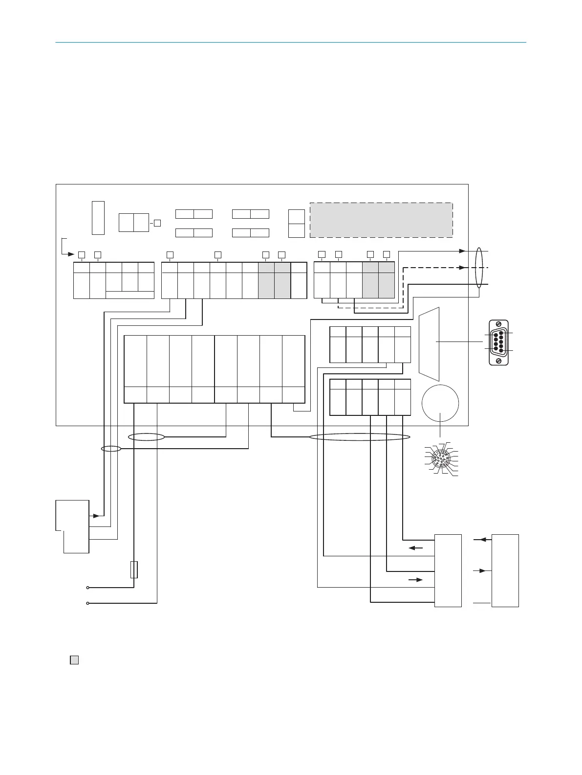
6.7 Connection modules
6.7.1 Using connection module CDB650-204
CDB650-204 connection module
Parameter memory module CMC600
(optional)
Term CAN
Term 485RS
SGND - GND
422 485
ONOFF
NO
YES
ONOFF
ONOFF
S2 S3
S7S6
S4
CMC
ONOFF
POWER
S1
30 31 32 33 34
CAN_H
CAN_L
T+
R+
GND
40 41 42 43 44
CAN_H
CAN_L
T‒/TxD
R‒/RxD
GND
AUX interface
5
1
9
6
U
IN
U
IN
GND
GND
Shield
Shield
Shield
Shield
1 2 3 4 5 6 7 8
LEDs
U
V
External
sensor for
read cycle
(e.g. photo-
electric
sensor)
U
V
Out
GND
Result 1
PLC
GND
Result 2
to the PC
to the
CLV69x-xxx0
(without heating)
Pin
2: RxD
3: TxD
5: GND
Host
TD‒
TD+
RD+
RD‒
TxD
Host
RxD
GND
GND
RS-232
RS-422
U
V
= DC 18V ... 30V for CLV69x-xxx0 (without heating) at terminal U
IN
=
U
IN
* after switch S1, protected with internal fuse F
2A T
F
17
16
10
11
12
15
14
6
5
4
13
7
8
9
1
2
3
SENSOR
50 51 52 53 54
RES/
OUT 3
RES/
OUT 4
Ext. Illum.
TR
L+
GND
20 21 22 23 24
GND
RES/
OUT 1
RES/
OUT 2
EXT.
OUT 1
EXT.
OUT 2
10 11 12 13 14 15 16 17 18
U
IN
*
U
IN
*
SGND
SGND
SGND
EXT.
IN 1
SENS/
IN 1
SENS/
IN 2
EXT.
IN 2
RS-232
= For the additional use of the external switching inputs and outputs, the optional CMC600 parameter memory module is required.
Max.
2A
F
ext
Figure 43: Wiring overview (1 switching input used) for CLV69x-xxx0 (without heating)
6
ELECTRICAL INSTALLATION
50
O P E R A T I N G I N S T R U C T I O N S | CLV69x 8014396/ZMG8/2017-07-04 | SICK
Subject to change without notice