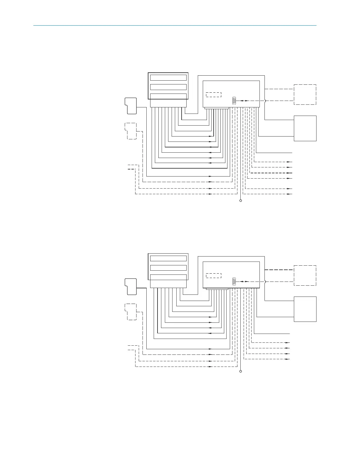
6.5 Connection diagrams
CDB650-204
“Sensor 2”
“Host 1” (serial)
“Aux 1” (serial)
“Result 2”
“Result 1”
“CAN”
“Result 4”
“Sensor 1”
“Ext. input 2”
*)
“Ext. input 1”
*)
“Result 3”
“U
V
”
“Sensor 2”
“Sensor 1”
“AUX”
PLC
CAN bus
PLC
“Result 1”
“Result 2”
PLC
PLC
“Result 3”
“Result 4”
PLC
PLC
“Ext. output 1”
*)
“Ext. output 2”
*)
Connection module
CDB650-204
Other
functions
“HOST 1” (serial)
“AUX 1” (serial)
RS-232
CMC600
*) For the additional use of the external switching inputs and outputs, the optional CMC600 parameter memory module is required.
HOST/PLC
Further data
processing
Configuration
Diagnostics
*)
“Ethernet” (Host 2/Aux 2)
RS-232/422/485
Ethernet
“Host 2”
Ethernet
“Aux 2”
U
V
U
V
= DC 18 ... 30V (CLV69x-xxx0)
U
V
= DC 21.6 ... 28.8V (CLV69x-xxx1)
Decoder
Scanner
Interface
CLV69x-xxx0 (without heating)
CLV69x-xxx1 (with heating)
Cloning plug
no. 2062452
PC
Photoelectric
sensor
Read cycle end
(alternative)
Incremental
encoder
Route increment
Photoelectric
sensor
Read cycle
Figure 36: Connection of the device to the CDB650-204 connection module
CDM420-0006
“U
V
”
“Sensor 2”
“Host 1” (serial)
“Aux 1” (serial)
“Result 2”
“Result 1”
“CAN”
“Sensor 2”
“Sensor 1”
“Ext. input 2”
*)
“Ext. input 1”
*)
“Sensor 1”
“AUX”
PLC
CAN bus
PLC
“Result 1”
“Result 2”
PLC
PLC
“Ext. output 1”
*)
“Ext. output 2”
*)
Connection module
CDM420-0006
Other
functions
“HOST 1” (serial)
“AUX 1” (serial)
RS-232
CMC600
*) For the additional use of the external switching inputs and outputs, the optional CMC600 parameter memory module is required.
HOST/PLC
Further data
processing
Configuration
Diagnostics
*)
“Ethernet” (Host 2/Aux 2)
RS-232/422/485
Ethernet
“Host 2”
Ethernet
“Aux 2”
U
V
U
V
= DC 18 ... 30V (CLV69x-xxx0)
U
V
= DC 21.6 ... 28.8V (CLV69x-xxx1)
Decoder
Scanner
Interface
CLV69x-xxx0 (without heating)
CLV69x-xxx1 (with heating)
Cloning plug
no. 2062452
PC
Photoelectric
sensor
Read cycle end
(alternative)
Incremental
encoder
Route increment
Photoelectric
sensor
Read cycle
Figure 37: Connection of the device to the CDM420-0006 connection module
6
ELECTRICAL INSTALLATION
44
O P E R A T I N G I N S T R U C T I O N S | CLV69x 8014396/ZMG8/2017-07-04 | SICK
Subject to change without notice