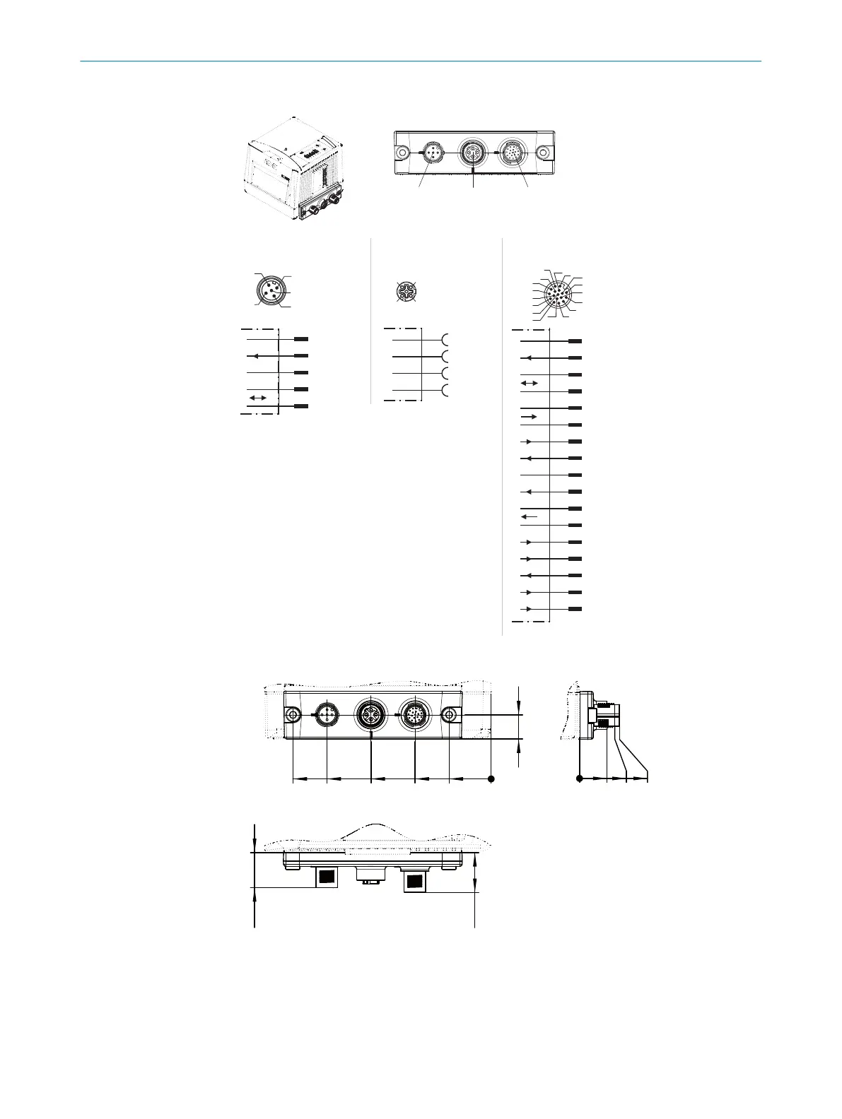
Cloning plug B, M12: Power/Serial Data/I/O/Ethernet/CAN 1
“CAN 1” connection,
V
S
, I
max in
= 4A
M12 male
connector,
5-pin,
A-coded
Shield
GND
V
S
1)2)
CAN1_L
CAN1_H
4
3
2
1
5
4
2
3
5
1
4
3
2
1
TD+
TD–
RD+
RD–
4
3
2
1
“Ethernet” connection
M12 female
connector,
4-pin,
D-coded
“HOST/AUX/I/0” connection,
V
s
, I
max in
= 1.5A
M12 male
connector,
17-pin,
A-coded
CAN1_L
CAN1_H
TD+ (RS-422/485), HOST
TD– (RS-422/485),
TxD (RS-232), HOST
V
S
1)
TxD (RS-232), AUX
RxD (RS-232), AUX
RD+ (RS-422/485), HOST
GND
RD– (RS-422/485),
RxD (RS-232), HOST
Result 1
Result 3
Result 4
Result 2
7
6
Sensor 2
Sensor 1
SensGND
4
3
2
1
5
8
9
10
11
12
13
14
15
16
17
Connection
“Ethernet”
Connection
“CAN 1”
Connection
“HOST/AUX/I/O”
no. 2062452
17
16
10
11
12
15
14
6
5
4
13
7
8
9
1
2
3
1) For CLV69x-xxx0 (without heating):
both contacts suitable for connection
of the supply voltage.
2) For CLV69x-xxx1 (with heating):
only this contact suitable for connection
of the supply voltage.
Sensor 1 and 2 = digital switching inputs
Result 1 ... 4 = digital switching outputs
Figure 26: Cloning plug B, M12: Power/Serial Data/I/O/Ethernet/CAN 1
12
0
21
38
60
82
99
20
18
0
13.7
18
20
All lengths in mm
[B]
CAN 1 Ethernet HOST/AUX/I/O
Figure 27: Cloning plug B, M12: Power/Serial Data/I/O/Ethernet/CAN 1
ELECTRICAL INSTALLATION 6
8014396/ZMG8/2017-07-04 | SICK O P E R A T I N G I N S T R U C T I O N S | CLV69x
39
Subject to change without notice