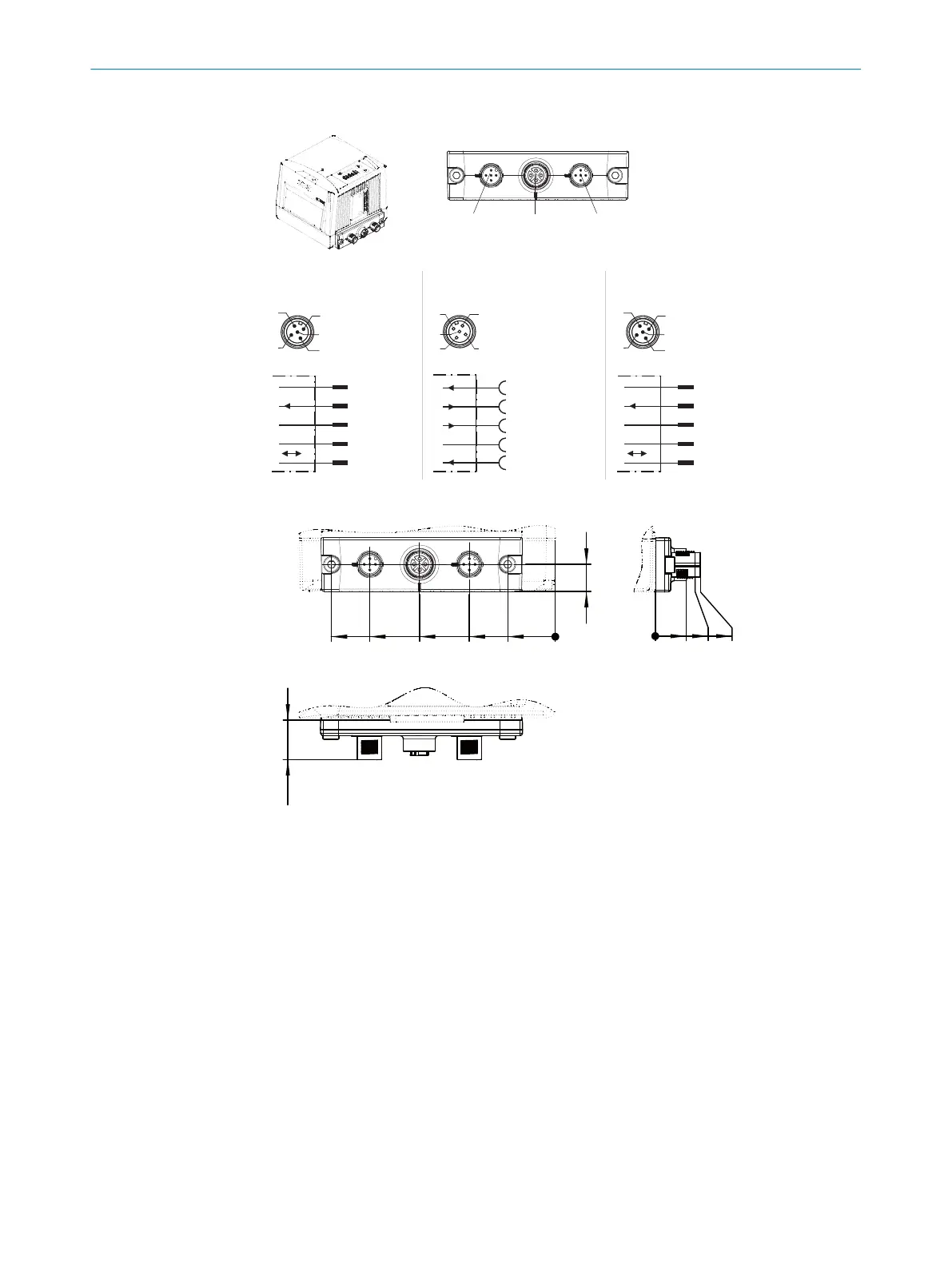
Cloning plug D, M12: Power/Serial AUX/IO/CAN 1/2
“CAN 1” connection,
U
V
, I
max in
= 4A
M12 male
connector,
5-pin,
A-coded
Shield
GND
V
s
1
CAN1_L
CAN1_H
4
3
2
1
5
4
2
3
5
1
“CAN 2” connection,
U
V
, I
max in
= 4A
M12 male
connector,
5-pin,
A-coded
Shield
GND
V
s
2
CAN2_L
CAN2_H
4
3
2
1
5
4
2
3
5
1
“Blower/AUX” connection
U
V
, I
max out
= 2 x LPS
M12 female
connector,
5-pin,
A-coded
Connection
“CAN 2”
Connection
“CAN 1”
Connection
“Blower/AUX”
4
2
3
5
1
3
2
1
4
5
RxD (RS-232), AUX
TxD (RS-232), AUX
V
s
OUT fan
Sensor 4 (IN 2
*)
)
GND
*) pin designation CLV480/490/CLX490
no. 2062454
Figure 30: Cloning plug D, M12: Power/Serial AUX/IO/CAN 1/2
12
0
21
38
60
82
99
18
0
13.7
18
20
All lengths in mm
[D]
CAN 1 Blower/AUX CAN 2
Figure 31: Cloning plug D, M12: Power/Serial AUX/IO/CAN 1/2
ELECTRICAL INSTALLATION 6
8014396/ZMG8/2017-07-04 | SICK O P E R A T I N G I N S T R U C T I O N S | CLV69x
41
Subject to change without notice