6.7.2 Using connection module CDM420-0006
ON
OFF
ON
OFF
ON
OFF
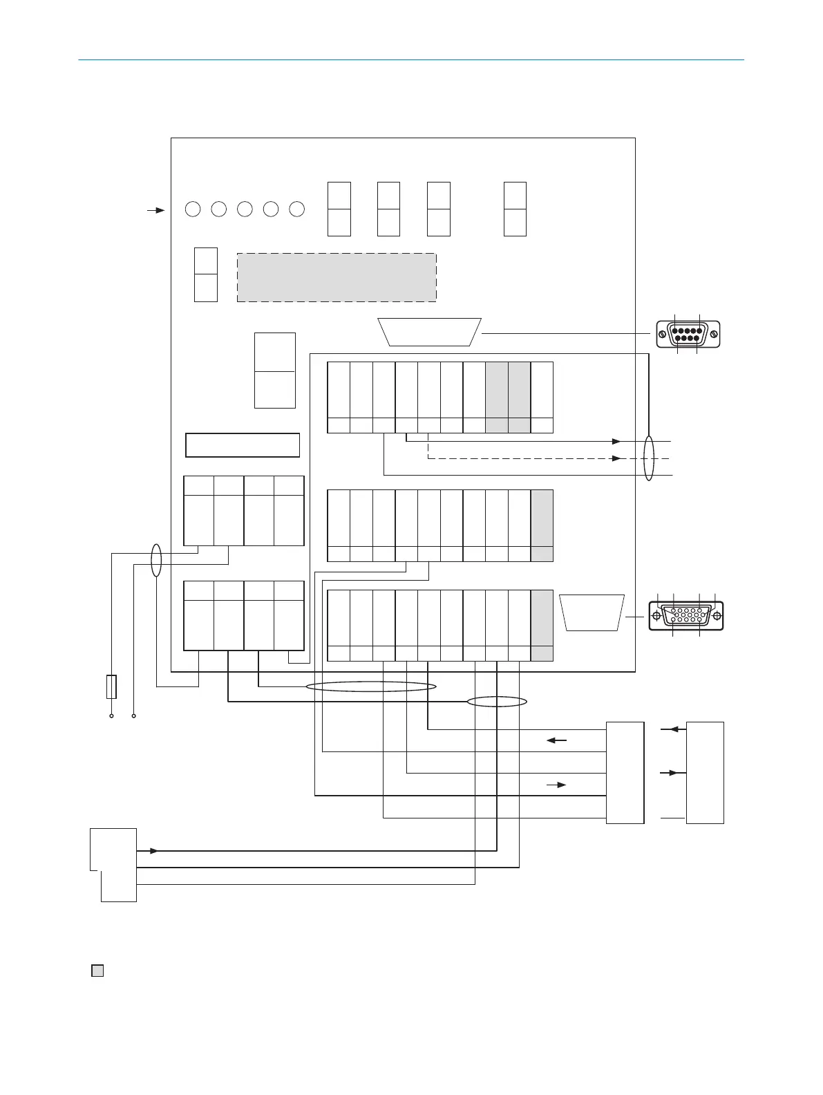
Connection module CDM420-0006
Parameter memory module CMC600
(optional)
2 A T
S8
No CMC ->
SCANNER
AUX interface
6110 5
1115
LEDs
31 32 33 34 35 36 37 38 39 40
T‒/TxD
R‒/RxD
+24V*
Sensor 1
Aux Out 1
GND
GND
SGND
CAN_H
CAN_L
11 12 13 14 15 16 17 18 19 20
Result 1
Result 2
Aux In 2
Aux In 1
SGND
GND
GND
SGND
internal
internal
21 22 23 24 25 26 27 28 29 30
T+
R+
+24V*
Sensor 2
Aux Out 2
GND
GND
SGND
CAN_H
CAN_L
1 2 3 4
+24V
+24V
GND
GND
5 6 7 8
Shield
Shield
Shield
Shield
POWER
Sensor 1
Sensor 2
Result 1
Result 2
S1
POWER
ON
OFF
S2 S3 S4 S6
ON
OFF
ON
OFF
RS485
Term422
TermCAN
SGND - GND
1 5
6 9
to PC
Pin
2: RxD
3: TxD
5: GND
Result 1
PLC
GND
Result 2
External sensor
for reading cycle
(e.g. photoelectric
sensor)
U
V
Out
GND
Host
TD‒
TD+
RD+
RD‒
TxD
Host
RxD
GND
GND
RS-232RS-422
RS-485
F
to CLV69x-xxx0
(without heating)
= For additional use of external switching inputs and outputs, the optional CMC600 parameter memory module is required.
U
V
= DC 18V ... 30V for CLV69x-xxx0 (without heating) at terminal +24V =
+24V* after switch S1, protected by internal fuse F
U
V
Max.
2A
F
ext
Figure 55: Wiring overview (1 switching input used) for CLV69x-xxx0 (without heating)
6
ELECTRICAL INSTALLATION
62
O P E R A T I N G I N S T R U C T I O N S | CLV69x 8014396/ZMG8/2017-07-04 | SICK
Subject to change without notice