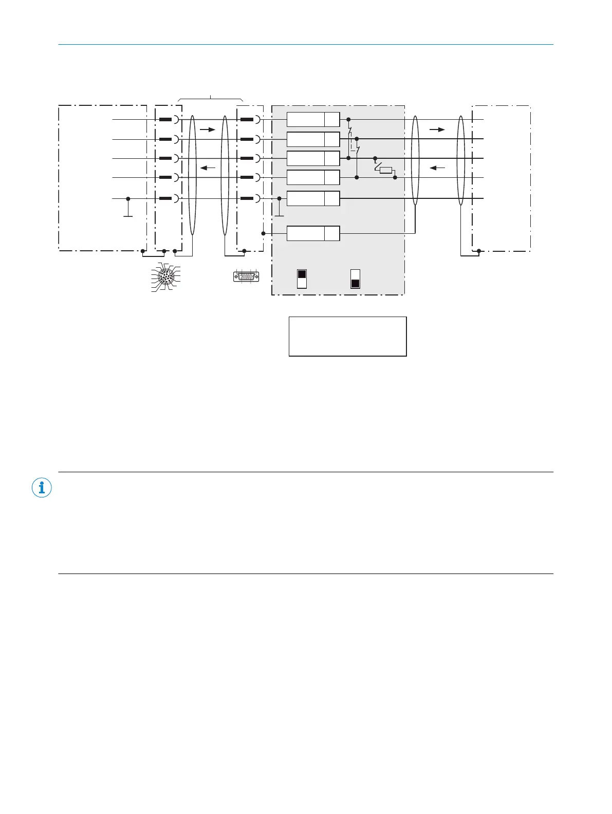
Wire RS-485 data interface of the CLV69x in the CDM420-0006 connection module
CLV69x CDM420-0006
Host
5
.
.
.
TD+
TD‒
RD+
RD‒
RD+
RD‒
TD+
TD‒
GND
GND
GND
11
12
1
5
8
9
6
7
6
24
T+
34
T‒/TxD
25
R+
35
R‒/RxD
36
GND
6
Shield
RS-485 RS-485
ON
OFF
S2 : RS 485
ON
OFF
S3: Term 422
S2
ON
S3
OFF
120 Ω
D-Sub-HD female
connector,
15-pin
M12 male
connector,
17-pin, A-coded
17
16
10
11
12
15
14
6
5
4
13
7
8
9
1
2
3
6110 5
1115
For CLV69x-xxx0 (without heating):
No. 2049764 (0.9m)
No. 2055419 (2m)
No. 2055420 (3m)
No. 2055859 (5m)
For CLV69x-xxx1 (with heating):
No. 2061480 (2m)
No. 2061605 (3m)
No. 2061481 (5m)
1) Dependent on type
S3: Term 422
Set to ON if the CLV69x is at the
end of the RS-485 bus cable.
Adapter cable
1)
Figure 61: Wire serial host interface RS-485
NOTE
Use of the RS-485 data interface:
•
The relevant interface drivers for the device comply with the standard for RS-422 and RS-485.
•
This operating mode is only permitted if all connected devices use a corresponding RS-485 protocol.
•
Activation of the interface in the device with the SOPAS ET configuration software (point-to-point).
•
This wiring is not permitted in the standard data output/protocol for the device. In case of doubt, contact
SICK Service.
6 ELECTRICAL INSTALLATION
68
O P E R A T I N G I N S T R U C T I O N S | CLV69x 8014396/ZMG8/2017-07-04 | SICK
Subject to change without notice