An individual function block converts 8 decimal values depending on the set value
r
ange. You can convert larger value areas by using several function blocks and configur‐
ing them accordingly.
Principle of operation
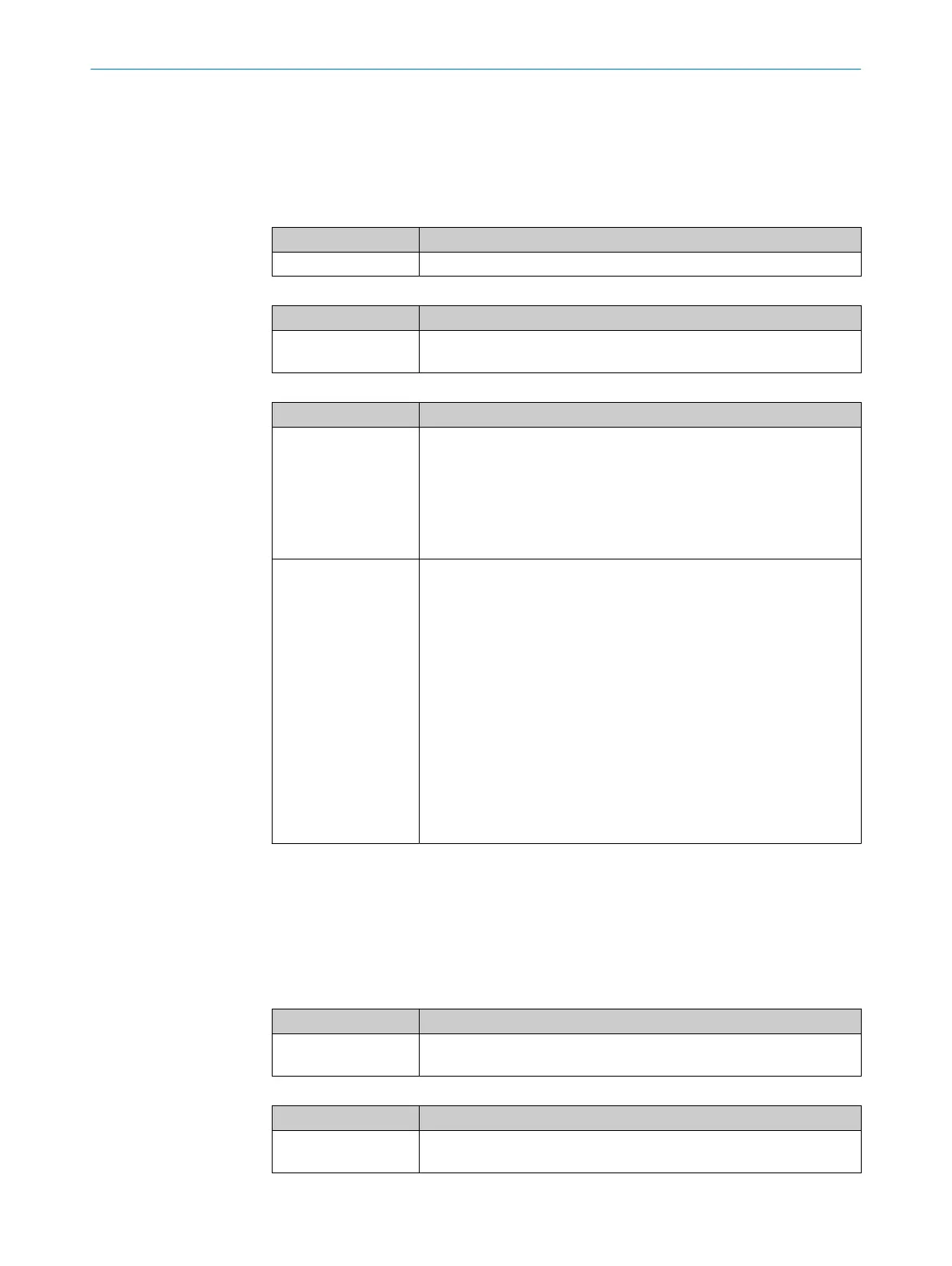
Table 36: Inputs
Input Description
Input Data type: UINT8
Table 37: Outputs
Output Description
Output value 0 … Out‐
put v
alue 7
Data type: Boolean
Depends on the Conversion mode parameter and the value at the input.
Table 38: Parameter
Parameter Description
Conversion mode
•
1-of
-N
Exactly 1 output = 1.
Example: Decimal value 5: Output 5 = 1, all other outputs = 0.
•
Equal-and-Lower
Outputs are 1 if they correspond to the decimal value or are lower
t
han the decimal value.
Example: Decimal value 5: Output 0 ... 5 = 1, all other outputs = 0.
Range offset 0 … 31
A function block covers 8 decimal values. You must use several func‐
tion blocks in order to be able to convert more than 8 decimal values.
With the Range offset parameter, you determine which value range the
function block converts.
You can use the following formula to calculate which decimal value
corresponds to a function block output:
Decimal value = N + 8 × R
•
N = Number of the output
•
R = Area offset
Example of output 0 with Range offset = 0:
•
Output 0 + 8 × 0 => output 0 = value 0
Example of output 7 with Range offset = 31:
•
Output 7 + 8 × 31 => output 7 = value 255
7.6.2.2.2 One-hot to UInt8 V1
Overview
T
he function block converts binary inputs into decimal values.
Principle of operation
Table 39: Inputs
Input Description
Value 0 … Value 7
(opt
ional)
Data type: Boolean
Table 40: Outputs
Output Description
Result Data type: UINT8
D
epending on the Conversion mode parameter.
CONFIGURATION 7
8024589/2020-11-10 | SICK O P E R A T I N G I N S T R U C T I O N S | Flexi Compact
61
Subject to change without notice