Table 53: Parameter
Parameter Description
Off delay time 0 … 300 s in 1-ms steps
1)
•
T
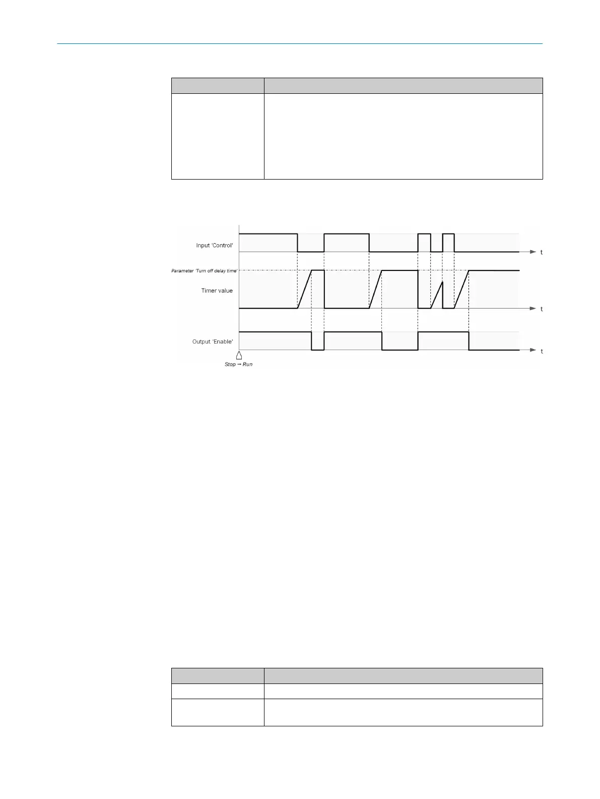
he switch-off delay time begins with a falling signal edge at the
Control input. If, after expiration of the configured switch-off delay
time, the Control input is still 0, the Enable output = 0.
•
If the Control input returns to 1 before expiration of the configured
switch-on delay time, the Enable output remains = 1. The timer for
the switch-off delay time is reset to 0.
1)
0 = No delay
Sequence/timing diagram
Figure 28: Sequence/timing diagram
Complementary information
If the configured delay time is less than or not a multiple of the logic execution time,
then the delay time extends to the next logic cycle.
If, during the first logic cycle, the Control input = 0, the Enable output = 0. The Enable
output remains 0 until the Control input = 1.
If, during the first logic cycle, the Control input = 1, the Enable output = 1. The Enable
output remains 1 until the Control input = 0 and the configured switch-off delay time
then expires.
7.6.2.3.3 Adjustable on-delay timer V1
Overview
T
his function block outputs a rising signal edge (0–1) at the Control input at the Enable
output after a delay.
You can configure up to four delay times. The delay times are activated via the associ‐
ated inputs. The total delay time at the Enable output is equal to the sum of all the
activated delay times.
Principle of operation
T
able 54: Inputs
Input Description
Control Data type: Boolean
Delay 1 … Delay 4
(opt
ional)
Data type: Boolean
CONFIGURATION 7
8024589/2020-11-10 | SICK O P E R A T I N G I N S T R U C T I O N S | Flexi Compact
65
Subject to change without notice