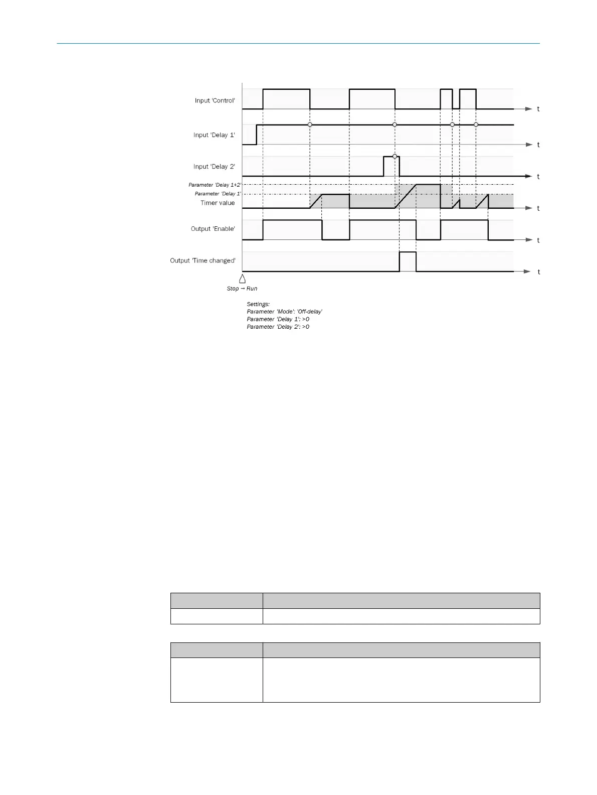
Sequence/timing diagram
Figure 30: Sequence/timing diagram
Complementary information
If t
he delay time selected using the Delay 1 … Delay 4 inputs is not a multiple of the logic
execution time, the delay time is extended to the next logic cycle.
If, during the first logic cycle, the Control input = 0, the Enable output = 0.
If, during the first logic cycle, the Control input = 1 and no delay time is configured, the
Enable output = 1.
If, during the first logic cycle, the Control input = 1 and a delay time > 0 is configured,
the function block sets the Enable output to 1 after the total delay time has elapsed.
7.6.2.3.5 Clock generator V1
Overview
T
he function block generates a pulsed signal. The elementary period and pulse dura‐
tion are configurable.
Principle of operation
Table 60: Inputs
Input Description
Enable Data type: Boolean
Table 61: Outputs
Output Description
Clock Data type: Boolean
•
If t
he Enable input = 1, then the Clock output pulsates.
•
If the Enable input = 0, then the Clock output becomes = 0.
7 CONFIGURATION
68
O P E R A T I N G I N S T R U C T I O N S | Flexi Compact 8024589/2020-11-10 | SICK
Subject to change without notice