Table 62: Parameter
Parameter Description
Rounding mode The input values of the Cloc
k period and Pulse time parameters are
rounded in such a way that a separation of at least one logic execution
time to one another and to 0 is maintained. This parameters specifies
whether to round up or round down.
The parameter setting is ignored if the rounding violates the permissi‐
ble limit values.
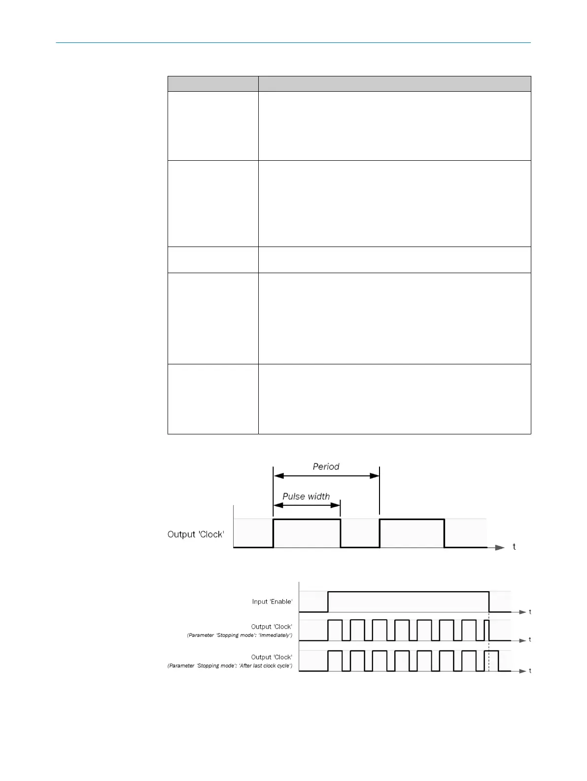
Stop Mode Determines the end of the pulsed signal.
•
Immedia
te
If the Enable in
put changes from 1 to 0, then the Clock output imme‐
diately changes to 0.
•
Af
ter last clock pulse
If the Enable in
put changes from 0 to 1, the function block will
complete the current elementary period.
Function block dis‐
abled
Clock period and Pulse time = 0.
Clock output = Enable input
Clock period An elementary period begins with the pulse duration. This is followed by
a pause
, the Clock output = 0. The next elementary period then begins.
see figure 31
The duration of the elementary period should be longer than the sum
of the pulse duration and logic execution time.
The parameter has an input value and an effective value. The configu‐
ration software corrects the input value to the correct effective value
based on the Rounding mode and Pulse time parameters.
Pulse time The pulse duration must be shorter than the elementary period. see
f
igure 31
The pulse duration can be shorter than the logic execution time.
The parameter has an input value and an effective value. The configu‐
ration software corrects the input value to the correct effective value
based on the Rounding mode and Clock period parameters.
Sequence/timing diagram
Figure 31: Parameter diagram
Figure 32: Sequence/timing diagram
CONFIGURATION 7
8024589/2020-11-10 | SICK O P E R A T I N G I N S T R U C T I O N S | Flexi Compact
69
Subject to change without notice