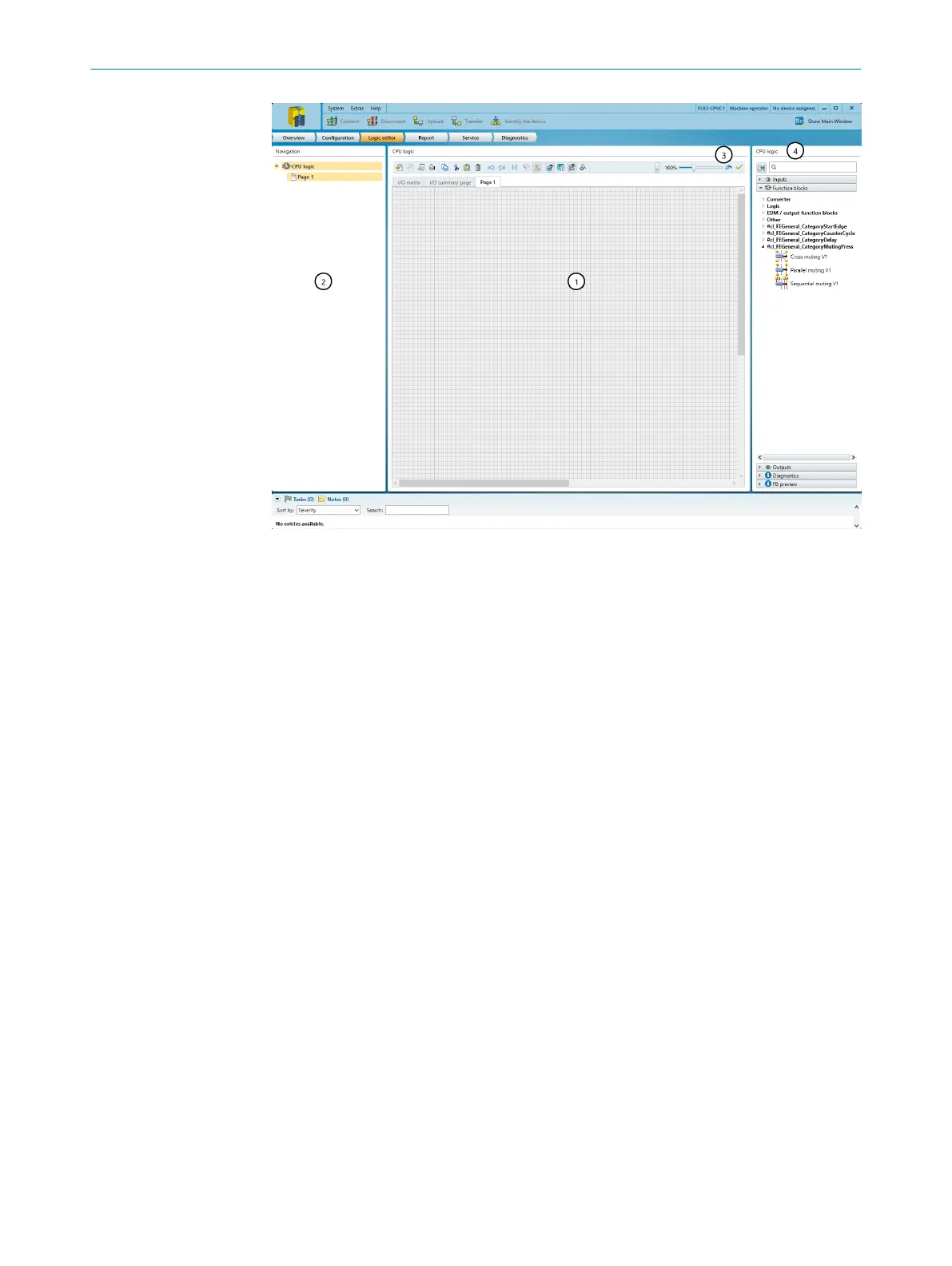
Figure 27: Logic editor
1
Work sheet
2
Navigation
3
Toolbar
4
CPU logic catalog
7.6.1 Inputs
Input elements
T
he Inputs selection window contains the following input elements for the logic program:
•
Jump addresses
•
The safety controller inputs that are in use
•
Bits of the output record of a gateway
•
Diagnostic elements
•
CPU marker
•
The Static 0 and Static 1 input elements
°
The output of the Static 0 element is always set to 0.
°
The input of the Static 1 element is always set to 1.
•
The First logic cycle input element
°
This input element is set to 1 during the very first logic cycle that is per‐
formed after each transition from the Stop status to the Run status.
°
The input element is set to 0 throughout all other logic cycles.
When used appropriately, the F
irst logic cycle input element initiates, for example,
initialization functions in the logic program.
Further topics
•
"CPU marker", page 107
•
"Jump addresses", page 107
•
"Connecting elements", page 108
7 C
ONFIGURATION
56
O P E R A T I N G I N S T R U C T I O N S | Flexi Compact 8024589/2020-11-10 | SICK
Subject to change without notice