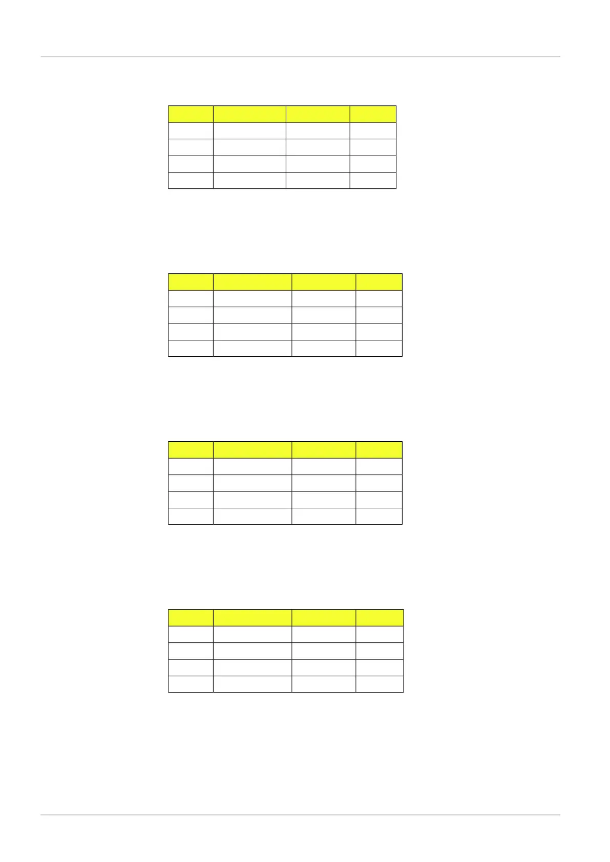
Table 5.1 Input Assembly 1
Total sizeOffset (bytes)Number/ sizeDatatype
8 bytes08/ 1 byte eachSINT
16 bytes88/ 2 bytes eachINT
20 bytes245/ 4 bytes eachDINT
20 bytes445/ 4 bytes eachREAL
Assembly 2 - medium result channel
Instance ID: 105
Size: 124 bytes
Table 5.2 Input Assembly 2
Total sizeOffset (bytes)Number/ sizeDatatype
12 bytes012/ 1 byte eachSINT
24 bytes1212/ 2 bytes eachINT
44 bytes3611/ 4 bytes eachDINT
44 bytes8011/ 4 bytes eachREAL
Assembly 3 - large result channel
Instance ID: 107
Size: 248 bytes
Table 5.3 Input Assembly 3
Total sizeOffset (bytes)Number/ sizeDatatype
24 bytes024/ 1 byte eachSINT
48 bytes2424/ 2 bytes eachINT
88 bytes7222/ 4 bytes eachDINT
88 bytes16022/ 4 bytes eachREAL
Assembly 4 - extra large result channel
Instance ID: 109
Size: 484 bytes
Table 5.4 Input Assembly 4
Total sizeOffset (bytes)Number/ sizeDatatype
44 bytes044/ 1 byte eachSINT
88 bytes4444/ 2 bytes eachINT
176 bytes13244/ 4 bytes eachDINT
176 bytes30844/ 4 bytes eachREAL
5.3.6 Assemblies command channel
The value that corresponds to each reference object can be found in the Reference object list
in the Main view.
Slim command channel
The Output assembly contains two parameters that are used for selecting reference object
and trigger inspections.
8015726/2013-11
©SICK AG • Advanced Industrial Sensors • www.sick.com • All rights reserved
Subject to change without notice
36
Reference Manual
EtherNet/IP
Interfaces
Inspector PIM