The value tags are replaced with a value whereas the container tags are used to group value
tags. The container tags do not generate any text on their own. It is the value tags inside the
container tags that generate the text.
Attribute value must always be enclosed in quotes.
There are three integer tags (<UINT1/>, <UINT2/>, <UINT3/>) for which the values can be
changed (in both Edit and Run mode) using the Command channel.
The <BLOB> container tag contains special functionality for presenting values for a certain
blob. The index value specifies which blob ROI:s result to present. The index order is the order
specified by the Sort by property configured on the Tools tab. The texts and value tags within
the <BLOB> tag will be repeated once for each found blob. If only the properties of a single
blob are wanted, this can be controlled with the index attribute. See Section A.3, “Container
specific tags” (page 40).
A.3 Container specific tags
All tags are listed in the table below. For each container tag, the available value tags are listed.
The binary column states the used data type when using binary output format. Some parts
of the formatting string, such as characters and ASCII tags, are only applicable for the ASCII
format and will be ignored when using binary format, this is also stated in the binary column.
Note
The Binary column in the tables below describes how the data should be interpreted when
received from the device.
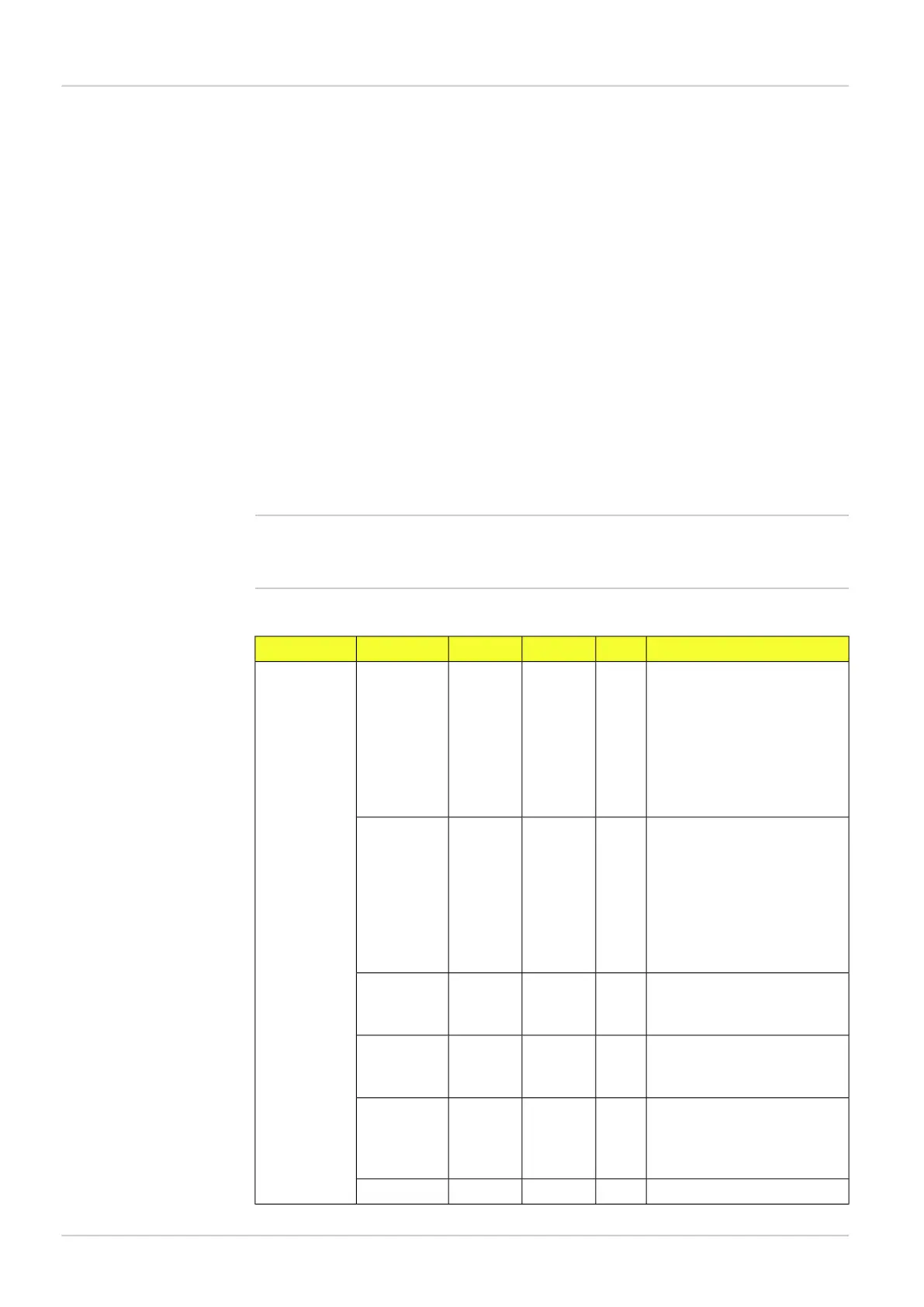
Table A.1 Container output string tags
CommentBinaryRangeAttributeValue tagContainer tag
X position of the reference
point. Note that this can be
REALcoordUnitXOBJECT_
LOC
outside the image and there-
fore negative. In “pixels” or
“mm” depending on attribute
“coordUnit” or configured value
in the Ethernet Result output dia-
log.
Y position of the reference
point. Note that this can be
REALcoordUnitY
outside the image and there-
fore negative. In “pixels” or
“mm” depending on attribute
“coordUnit” or configured value
in the Ethernet Result output dia-
log.
In degrees or radians depend-
ing on the configured value in
the Ethernet Result output dialog.
REAL[-180,
180]
unitROTATION
Scale factor of analyzed live
image compared to taught ref-
erence object.
REAL[0.8, 1.2]SCALE
Score view in percent how well
of the object is found in the
REAL[0, 100]SCORE
object locator due to match
setting
0=not found, 1=foundUSINT{0, 1}DECISION
8015726/2013-11
©SICK AG • Advanced Industrial Sensors • www.sick.com • All rights reserved
Subject to change without notice
40
Reference Manual
Result output formatting
Appendix
Inspector PIM